EV-STRUCTURAL-ARDZ
Sensor for Structural Monitoring
Overview
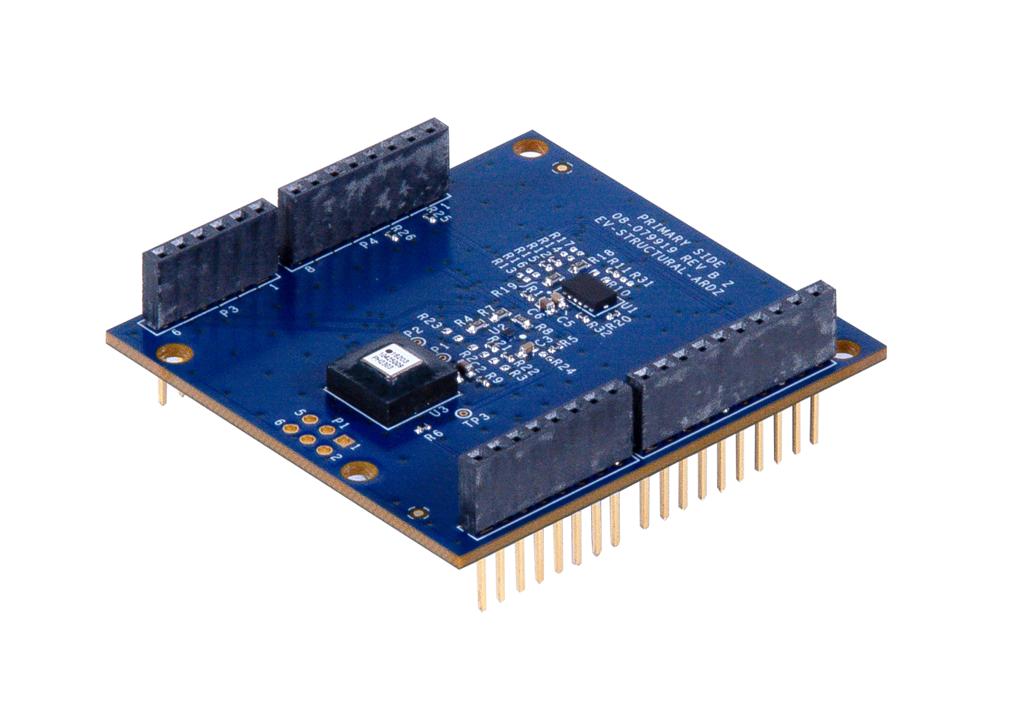
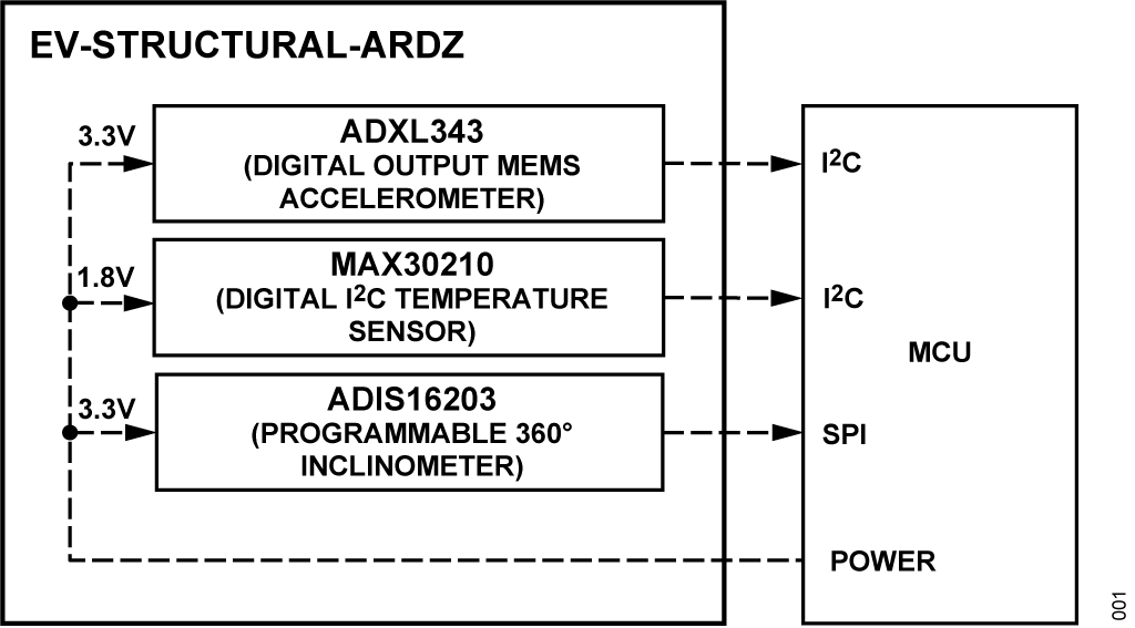
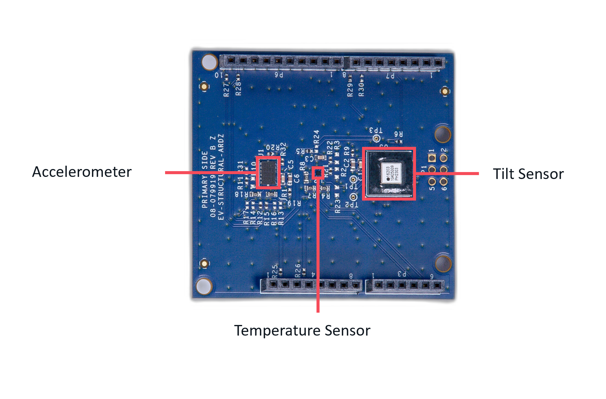
The EV-STRUCTURAL-ARDZ is a vibration sensor that uses the ADXL343 digital output MEMS accelerometer chip and the ADIS16203 programmable 360° inclinometer. Aside from providing vibration data, this board also features the MAX30210 digital temperature sensor which gives the option to shut down sensitive machines and equipment for smart motor sensing applications. This vibration sensor can also detect if the horizontal position of the sensor changes, which points towards a collapse of the structure where the sensor was deployed.
Features
Temperature Sensor |
|---|
±0.1°C accuracy from +20°C to +50°C |
±0.15°C accuracy from -20°C to +85°C |
High and low temperature alarms |
Accelerometer |
Built-in motion detection features make tap, double-tap, activity, inactivity, and free-fall detection trivial |
Multipurpose accelerometer with 10- to 13-bit resolution for use in a wide variety of applications |
Inclinometer |
Digital self-test function |
Configurable alarm function |
±180 output format option |
Applications
Smart motor sensor
Tilt sensing, inclinometers
Platform control, stabilization, and leveling
Motion/position measurement
Monitor/alarm devices (security, medical, safety)
Block Diagram
Hardware Design
Components and Connections
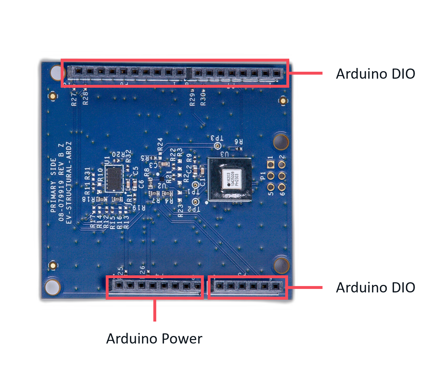
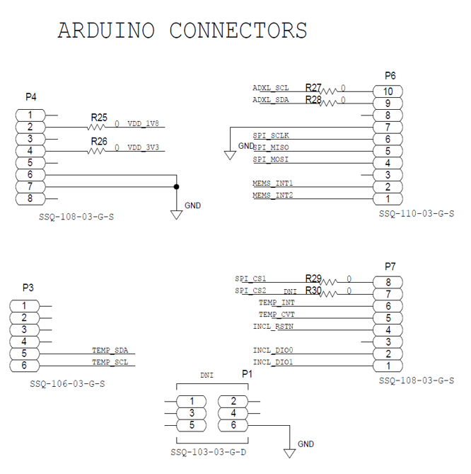
Digital Interface (Arduino)
The Arduino interface is a standardized digital interface for various digital communication protocols such as SPI, I2C, and UART. These interface types were standardized by Arduino, which is hardware and software company. Complete details on the PMOD specification can be found here.
The pin map for the Arduino pins is described in the table and its schematic diagram below.
Sensor Device
The board comes with the ADXL343 3-Axis MEMS Accelerometers, ADIS16203 Programmable 360° Inclinometer, and MAX30210 ±0.1°C Accurate, 16-Bit Digital I2C Temperature Sensor.
Applications
The EV-STRUCTURAL-ARDZ can be used with the MAX32670-SX-ARDZ Base Board, which is a long-range wireless radio development platform based on MAX32670 ultralow power ARM Cortex-M4 microcontroller and SX1261 RF transceiver.
Using these platforms together enables users to design solutions based on low-power, long range proprietary radio communication technique.
To learn more about the Long Range Wireless Radio solution developed by Analog Devices, visit the AD-MAX32SXWISE-SL Long Range Wireless Radio Development Kit User Guide.
PHASE 1: Hardware Setup
Note that this setup only applies for MAX32670-SX-ARDZ Base Board. Users may use a different base board or microcontroller, however the firmware built for this demo application cannot be used as this is specifically designed for the MAX32670-SX-ARDZ.
Equipment Needed
One (1) MAX32670-SX-ARDZ Base Board
One (1) EV-FLOWMETER-ARDZ Sensor Node
One (1) MAX32625PICO Rapid Development Platform with 10-pin ribbon cable with firmware image
One (1) CR123A Battery or any equivalent external DC power supply (+3V to +4.7V). Note that this is not included in the kit
One (1) Micro USB to USB cable
Host PC (Windows 10 or later)
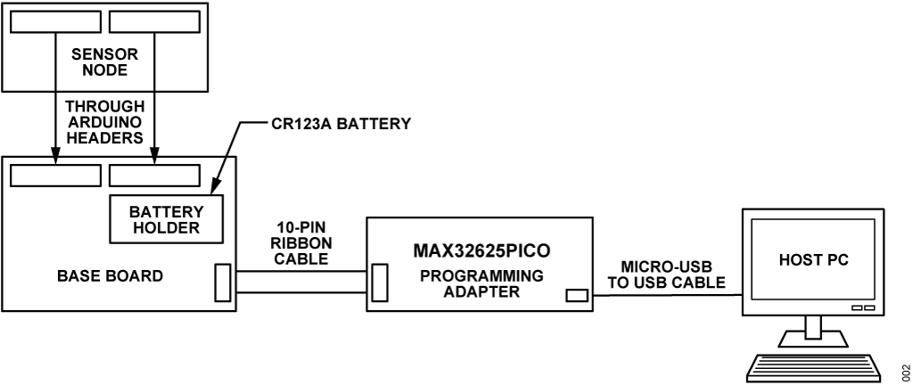
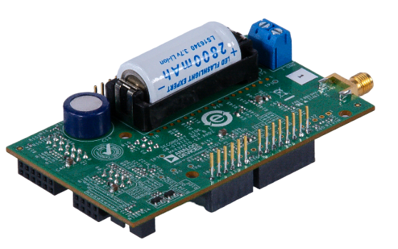
Insert one CR123A battery (3V to 4.7V) into the battery holder (BT1 connector) of the MAX32670-SX-ARDZ Base Board.
Make sure to check for the battery polarity in the BT1 connector, refer to the figure below. The DS3 LED will light up indicating that you have inserted the battery correctly and that power is provided in the base board.
Connect the EV-STRUCTURAL-ARDZ Sensor Node to the MAX32670-SX-ARDZ Base Board by aligning the corresponding Arduino headers on each board.
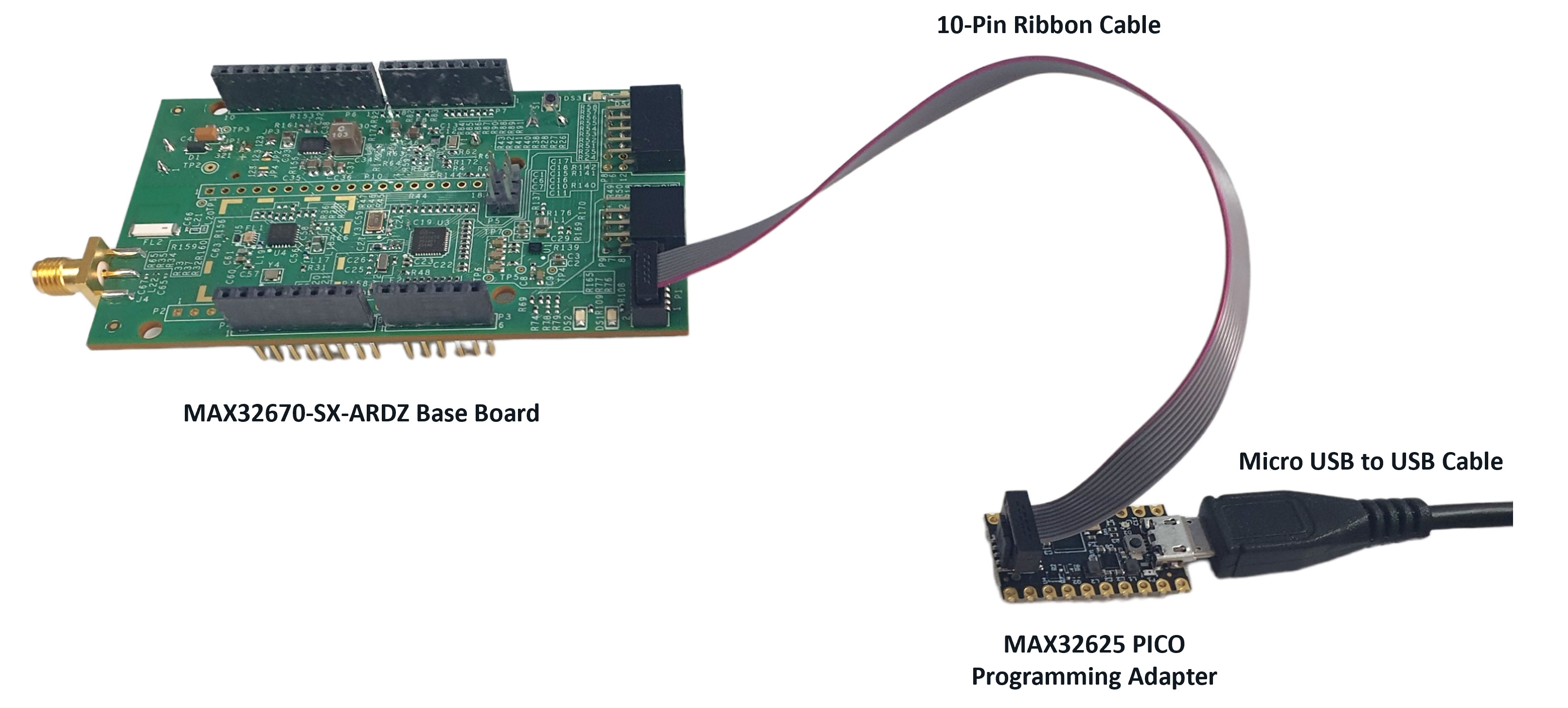
Connect the MAX32625PICO programming adapter to the MAX32670-SX-ARDZ Base Board through the 10-pin ribbon cable.
Tip
Make sure that the MAX32625PICO programming adapter has been flashed with the correct image before connecting it to the MAX32670-SX-ARDZ Base Board.
How to flash the firmware image in the MAX32625PICO
Download the firmware image: MAX32625PICO Firmware Image for MAX32670
Do not connect the MAX32625PICO to the MAX32670-SX-ARDZ Base Board yet.
Connect the MAX32625PICO to the Host PC using the micro USB to USB cable.
Press the button on the MAX32625PICO. (Do not release the button until the MAINTENANCE drive is mounted).
Release the button once the MAINTENANCE drive is mounted.
Drag and drop (to the MAINTENANCE drive) the firmware image.
After a few seconds, the MAINTENANCE drive will disappear and be replaced by a drive named DAPLINK. This indicates that the process is complete, and the MAX32625PICO can now be used to flash the firmware of the MAX32670-SX-ARDZ Base Board.
Connect the MAX32625PICO programming adapter to the Host PC using the micro USB to USB cable.
Once you have completed this setup, proceed to PHASE 2 found in ADI Long Range Wireless Radio Software User Guide.
Resources
Design and Integration Files
Download
EV-STRUCTURAL-ARDZ Design Support Package Rev. B
Schematic
Bill of Materials
Layout
Fabrication Files
Help and Support
For questions and more information about this product, connect with us through the Analog Devices Engineer Zone.