Follow the steps in this order, to avoid damaging the components:
Connect the EVAL-ADRV9002 FMC board to the FPGA carrier FMC socket.
On the FMC card, set the switch to select clock source between:
an on-board 38.4 MHz VCTCXO (default)
external (via J501) 10 MHz to 1000 MHz / +13 dBm
Connect the UART port of ZedBoard to a PC via Micro-USB (J14).
Insert the SD card into the slot, located on the underside of ZedBoard (J12).
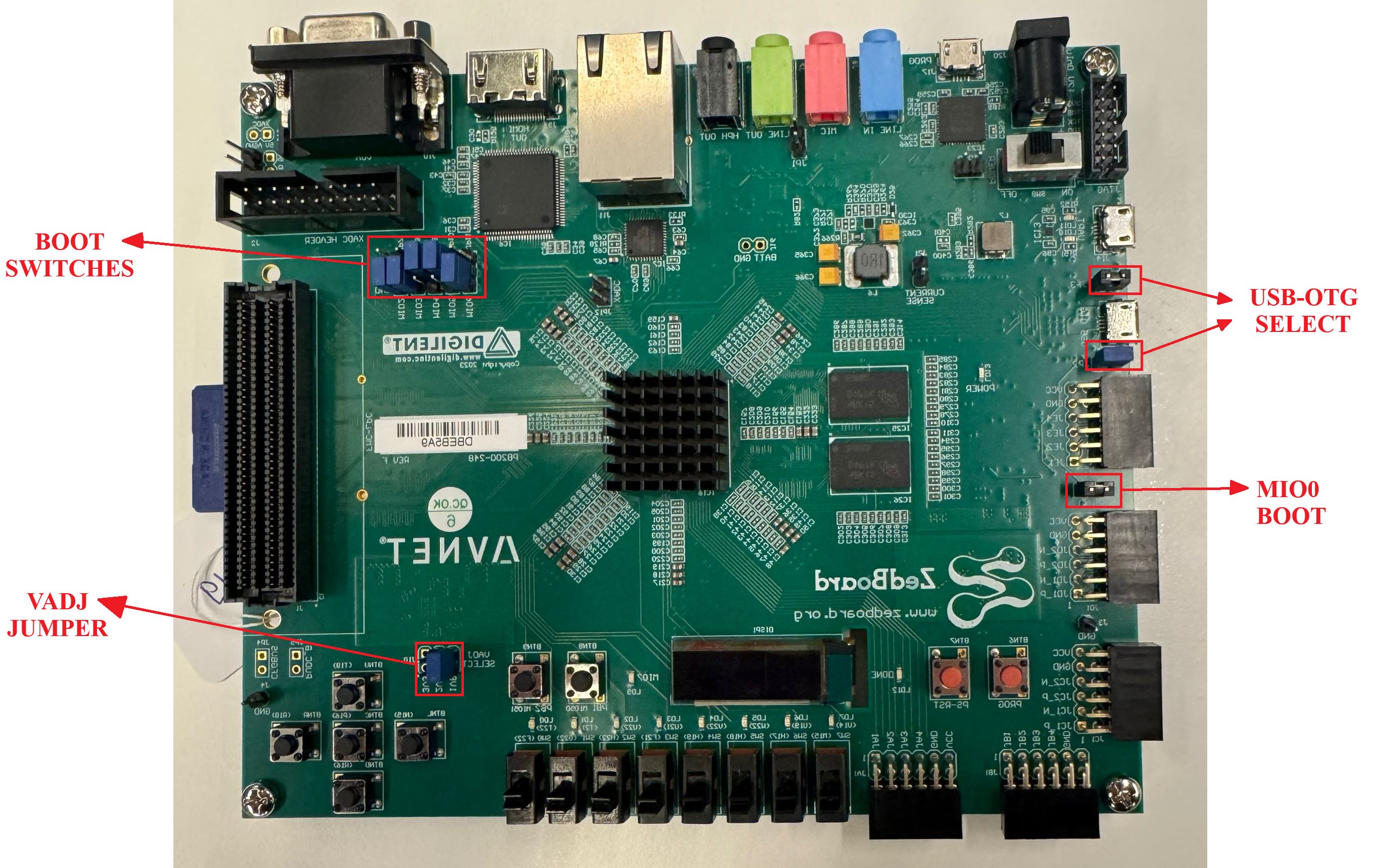
Configure ZedBoard for SD BOOT: boot (JP7-JP11) and MIO0 (JP6) jumpers set to SD card mode, in accordance with the picture shown below.
Connect 12V power supply to barrel jack.
Turn on the power switch (SW8) on the FPGA board. Green Power LED (LD13) should illuminate.
Wait approximately 15 seconds. The blue Done LED (LD12) should illuminate.
Observe kernel and serial console messages on your terminal.
You can also connect a monitor, keyboard and mouse directly to the board for a local connection. The UART connection is still recommended for debugging purposes. For the local connection, follow these additional steps:
Plug your HDMI display device into the HDMI Video Connector (J9).
Plug your USB mouse/keyboard into the USB OTG Micro-B Connector (J13). You will have to use a USB hub to connect both mouse and keyboard. Some keyboards have a mouse or touch pad sharing the same USB connection or wireless dongle. This can be used to eliminate the use of a USB hub.
Wait another ~30 seconds for the HDMI display device to start showing signs of life.
Note
The USB OTG circuit requires specific jumper settings for Host mode. Ensure the following jumper settings on the ZedBoard (these are the defaults; verify them if USB is not working):
JP2 → Short (enables 5V output to USB OTG connector)
JP3 → Short (Host mode)