EVAL-CN0410-ARDZ Shield Demo
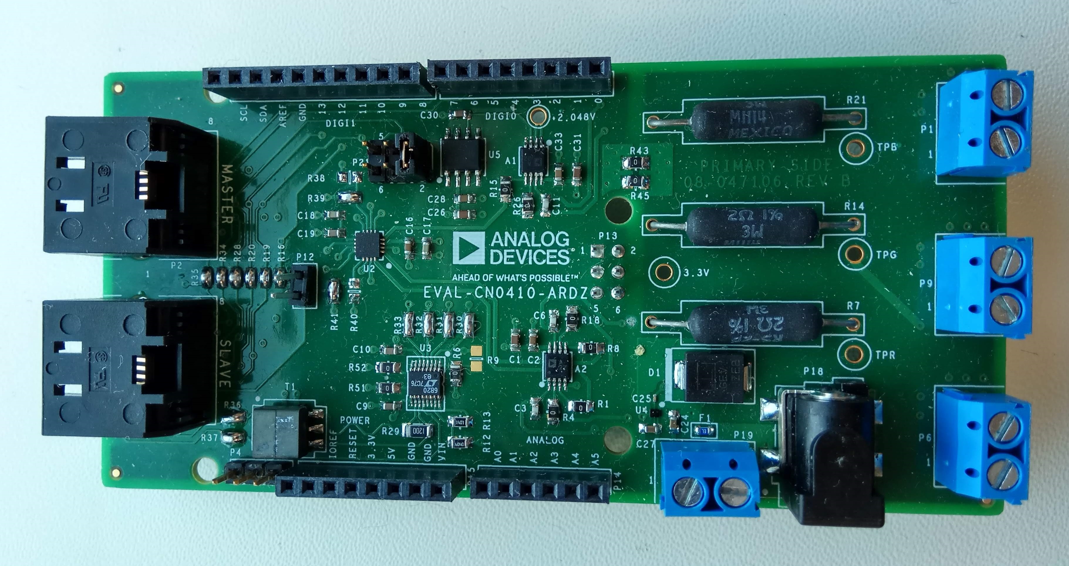
CN0410 is an Arduino compatible shield that is optimized for smart agriculture to control current passing through LED’s. The CN0410 is used along the the CFTL-LED Bar that has LED’s with specific wavelengths that plants utilize.
The circuit shown below is a complete 3-channel single-supply, 16-bit unbuffered voltage output DAC that maintains ±2 LSB integral and differential nonlinearity by utilizing a CMOS DAC. This circuit has a voltage to current conversion that controls the amount of current passing through an LED by using a MOSFET in its configuration. The circuit also has an isoSPI repeater that allows multiple boards to be controlled with a single master.
Demo Requirements
The following is a list of items needed in order to replicate this demo.
Hardware
EVAL-ADICUP3029
EVAL-CN0410-ARDZ
Mirco USB to USB cable
PC or Laptop with a USB port
Software
ADICUP3029_demo_CN0410 software
CrossCore Embedded Studio (2.6.0 or higher)
ADuCM302x DFP (2.0.0 or higher)
ADICUP3029 BSP (1.0.0 or higher)
Serial Terminal Program (Required for running in release mode only)
Such as Putty or Tera Term
Setting up the Hardware
Chip Select
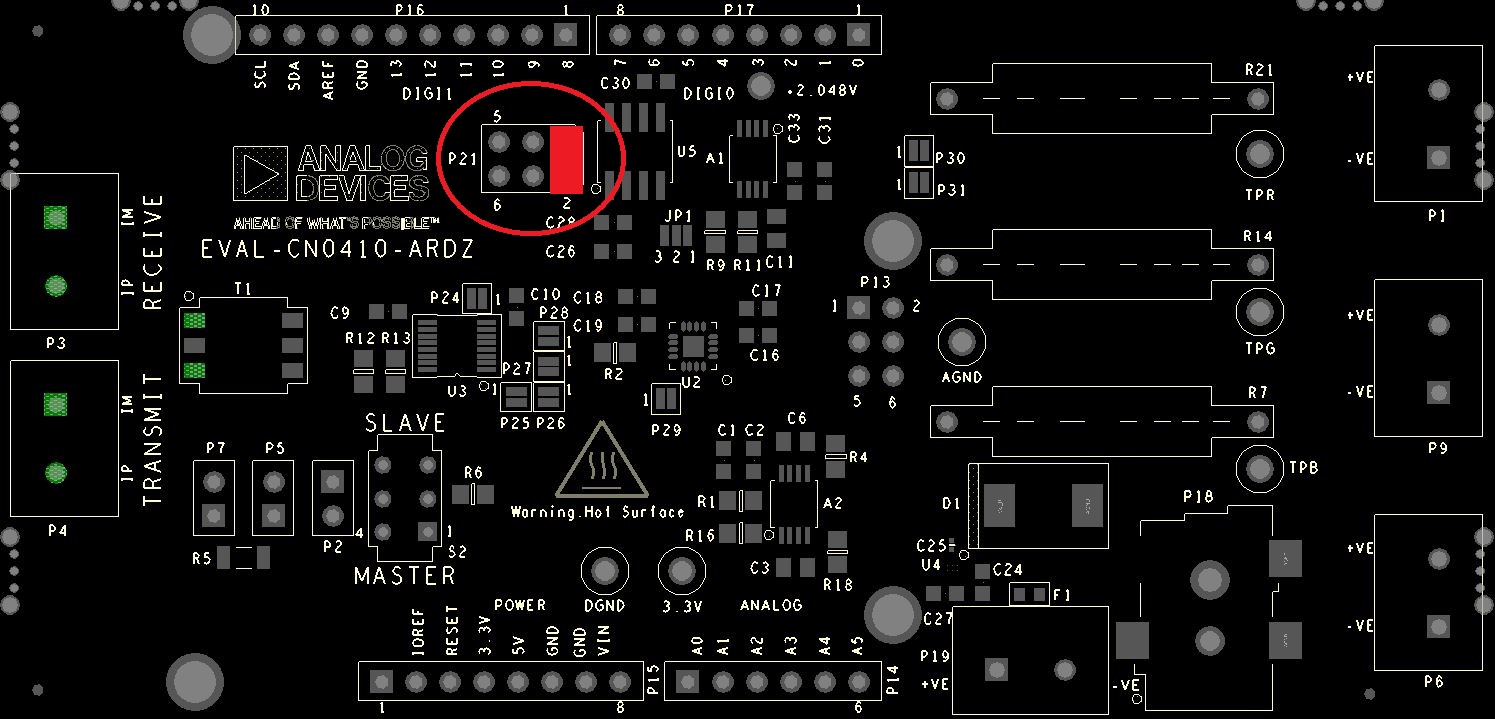
The chip select pin of the AD5686 is hardware configurable and routed to 3 general purpose I/O pins on the board. Use the table below to change the location of the chip select simply by moving the shunt on P21, and ensuring the software is configured the same way. By default the chip select is located on GPIO 8. This feature allows multiple boards using SPI communications protocol to be stacked on top of each other.
Chip Select (P21) |
GPIO (P16) |
|---|---|
Pins 1 & Pin 2 |
GPIO 8 |
Pins 3 & Pin 4 |
GPIO 9 |
Pins 5 & Pin 6 |
GPIO 10 |
Configuring the Software
The software for EVAL-CN0410 does not require any particular configurations in order to setup the application. The only setting that the user could make would be the selection of the CS pin. This can be done by modifying the SYNC_PORT and SYNC_PIN inside adi_cn0410.h.
#define SYNC_PORT   ADI_GPIO_PORT1 //this is the CS pin
#define SYNC_PIN    ADI_GPIO_PIN_12
Outputting Data
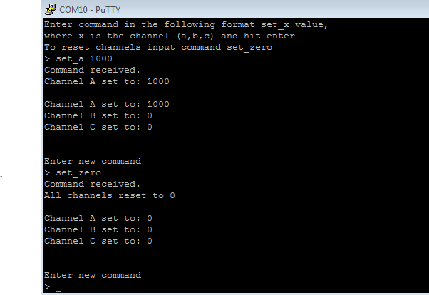
After the application starts the user can send commands to set the output of the DAC channels. Available commands:
set_a value
set_b value
set_c value
set_zero - resets all channels to 0
The value can be between 0 and 65535.
Serial Terminal Output
Once the hardware and software is configured, user needs to follow on screen instructions to run EVAL-CN0410 demo.
Following is the UART configuration.
Select COM Port
Baud rate: 9600
Data: 8 bit
Parity: none
Stop: 1 bit
Flow Control: none
Obtaining the Software
There are two basic ways to program the ADICUP3029 with the software for the CN0410.
Dragging and Dropping the .Hex to the Daplink drive
Building, Compiling, and Debugging using CCES
Using the drag and drop method, the software is going to be a version that Analog Devices creates for testing and evaluation purposes. This is the EASIEST way to get started with the reference design
Importing the project into CrossCore is going to allow you to change parameters and customize the software to fit your needs, but will be a bit more advanced and will require you to download the CrossCore toolchain.
The software for the ADuCM3029_demo_cn0410 can be found here:
Download
Prebuilt CN0410 Hex File
Complete CN0410 Source Files
How to use the Tools
The official tool we promote for use with the EVAL-ADICUP3029 is CrossCore Embedded Studio. For more information on downloading the tools and a quick start guide on how to use the tool basics, please check out the Tools Overview page.
Importing
For more detailed instructions on importing this application/demo example into the CrossCore Embedded Studio tools, please view our How to import existing projects into your workspace section.
Debugging
For more detailed instructions on importing this application/demo example into the CrossCore Embedded Studio tools, please view our How to configure the debug session section.
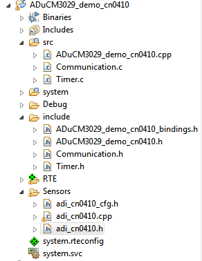
Project Structure
The project is structured in 3 sections :
source - that contains the communication, timer and main sections
include - header files
sensors - with DAC driver