Command Line Interpreter Demo
The ADuCM360_demo_cli is a Command Line Interpreter (CLI) demo project for the EVAL-ADICUP360 base board, created using the GNU ARM Eclipse Plug-ins in Eclipse environment.
General description
The purpose of this project is to help you to get used with UART peripheral of ADuCM360 microcontroller. The source code example can serve as a template for a resident command line interpreter, complementing any other user application functionality. Interrupt-based receiving of text commands from the UART is implemented. As soon as a command is entered, an execution request flag is raised to signal the main loop. The commands are recognised and may be executed immediately or later depending on the priority of the current tasks.
You can use any Terminal session you want, such as Putty or Serial Terminal with Eclipse Kepler (incorporated in Eclipse environment).
A serial connection of a PC to the EVAL-ADICUP360 board using the user USB connector is required to test and use the CLI application (EVAL-ADICUP360 board incorporates an FTDI USB-to-serial converter). Any terminal application run on a PC at 9600-8-N-1 without flow control can be used to ‘talk’ to the EVAL-ADICUP360 board. After connecting and sending CR (by pressing Enter), the command prompt ‘>>’ and a welcome message should appear.
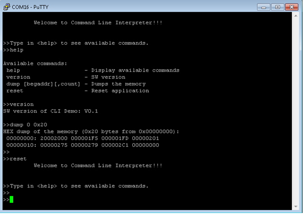
Available commands
Command |
Description |
|---|---|
help |
Display available commands |
version |
Display SW version of CLI project |
dump [begaddr] [count] |
Display up to 0x40 consecutive byte-size locations from any address of the ADuCM360 memory space. One should be careful not to request locations which are not decoded because the hardware_fault exception code will block the board. |
reset |
Perform a HW reset which also initialize the application |
Demo Requirements
The following is a list of items needed in order to replicate this demo.
Hardware
EVAL-ADICUP360
Mirco USB to USB cable
PC or Laptop with a USB port
Software
ADuCM360_demo_cli software
CrossCore Embedded Studio (2.7.0 or higher)
ADuCM36x DFP (1.0.2 or higher)
CMSIS ARM Pack (4.3.0 or higher)
Serial Terminal Program
Such as Putty or Tera Term
Setting up the hardware
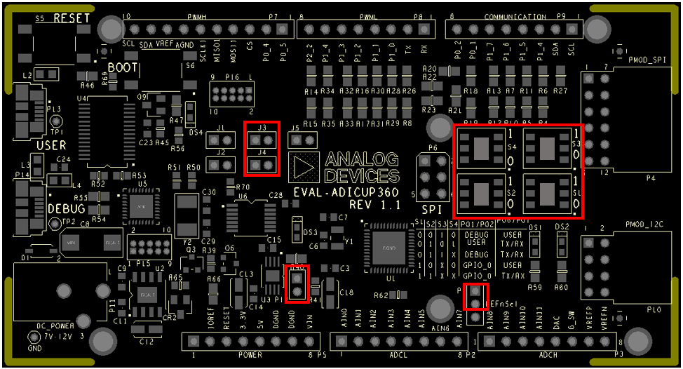
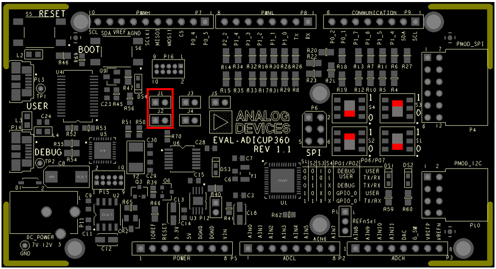
In order to program the EVAL-ADICUP360 you need to use the DEBUG USB. The jumper set up is shown in the next figure. The important jumpers are highlighted in red.
The ADuCM360_cli_demo can connect to the serial port of a PC through two different USB ports on the board:
USER USB (using P0.1, P0.2 or P0.6, P0.7 of the ADuCM360)
DEBUG USB (only P0.1, P0.2 of the ADuCM360)
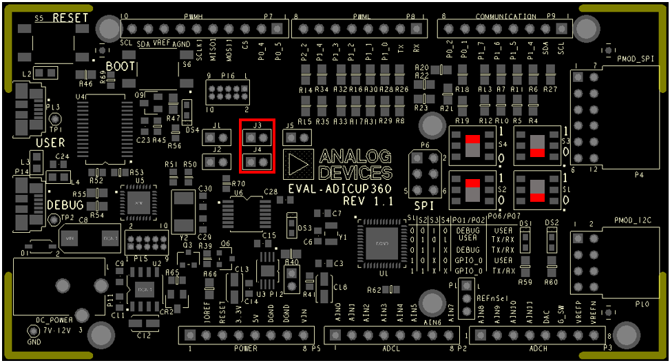
A bank of jumpers provided near the PMOD ports of the EVAL-ADICUP360, makes this easy to configure. The jumpers required for particular configurations are provided in the images below. Ensure that the pins you select in the hardware configuration, also match what is in your software pin definition.(UART_PINS)
Using UART via USER USB (P0.1, P0.2)
Using UART via USER USB (P0.6, P0.7)
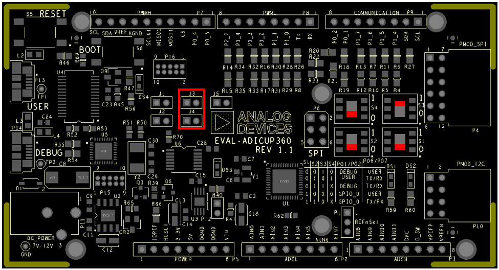
Using UART via DEBUG USB (P0.1, P0.2)
Note
If using UART in USER USB configuration, you first need to program the board using DEBUG USB
Note
If using UART in DEBUG USB configuration you first need to program the board using DEBUG USB and after the program runs on target, you need to change jumper (J1 and J2) positions
Obtaining the Source Code
There are two basic ways to program the ADICUP360 with the software for the CLI Demo.
Dragging and Dropping the .Bin to the MBED drive
Building, Compiling, and Debugging using CCES
Using the drag and drop method, the software is going to be a version that Analog Devices creates for testing and evaluation purposes. This is the EASIEST way to get started with the reference design.
Importing the project into CrossCore is going to allow you to change parameters and customize the software to fit your needs, but will be a bit more advanced and will require you to download the CrossCore toolchain.
The software for the ADuCM360_demo_cli demo can be found here:
Download
Prebuilt CLI Demo Bin File
Complete CLI Demo Source Files
Note
For more information on importing, debugging, or other tools related questions, please see the tools user guide.
Configuring the Software Parameters
UART Configuration Settings can be found in the Communications.h file.
/* UART pins */
#define UART_PINS_12            1  /* Connected to P0.1, P0.2 */
#define UART_PINS_67            2  /* Connected to P0.6, P0.7 */

#define UART_PINS    UART_PINS_12  /* Select UART pin destination */

/* The serial port may be used in polling or interrupt mode */
#define UART_MODE UART_INT_MODE
Outputting Data
Serial Terminal Output
In order to view the data, you must flash the program to the EVAL-ADICUP360.
Once complete you will need to switch the USB cable from the DEBUG USB (P14) to the USER USB (P13).
Then follow the UART settings below with the serial terminal program.
Following is the UART configuration.
Select COM Port
Baud rate: 9600
Data: 8 bit
Parity: none
Stop: 1 bit
Flow Control: none
Available commands
The user must type the word <help> in order to bring up the CLI menu shown below.
Command |
Description |
|---|---|
help |
Display available commands |
version |
Display SW version of CLI project |
dump [begaddr] [count] |
Display up to 0x40 consecutive byte-size locations from any address of the ADuCM360 memory space. One should be careful not to request locations which are not decoded because the hardware_fault exception code will block the board. |
reset |
Perform a HW reset which also initialize the application |
How to use the Tools
The official tool we promote for use with the EVAL-ADICUP360 is CrossCore Embedded Studio. For more information on downloading the tools and a quick start guide on how to use the tool basics, please check out the Tools Overview page.
Importing
For more detailed instructions on importing this application/demo example into the CrossCore Embedded Studios tools, please view our How to import existing projects into your workspace section.
Debugging
For more detailed instructions on importing this application/demo example into the CrossCore Embedded Studios tools, please view our How to configure the debug session section.
Project Structure
The ADuCM360_demo_cli project Project structure is shown below:
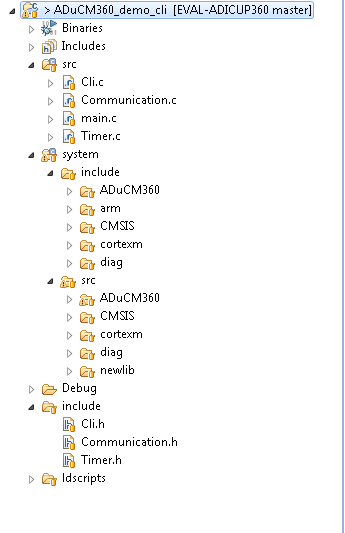
This project contains: initialization part - disabling watchdog, setting system clock, enabling clock for peripheral; UART interrupt service; port configuration for UART use; UART read/write management; command line interpreter application.
In the src and include folders you will find the source and header files related to CLI application. You can modify as you wanted those files. The Communication.c/h files contain UART specific data, meanwhile the cli.c/h files contain the command interpreter data.
The RTE folder contains device and system related files:
Device Folder – contains low levels drivers for ADuCM360 microcontroller.(try not to edit these files)
system.rteconfig - Allows the user to select the peripherial components they need, along with the startup and ARM cmsis files needed for the project.