gr-ofdmradar - OFDM Radar on MxFE Platforms
This documentation covers building an OFDM radar system on a ZCU102 + AD9081 using GNU Radio and IIO.
Software/Hardware quickstart
Required hardware
TX and RX antennas with cables
Optional RF components (receiver LNA, TX PA)
Linux development machine (x86_64)
Required software
Vivado 2020.2+ (with Vitis SDK)
MPSoC license (included with eval kit)
Recent software build toolchain
Preparing ZCU102 boot files
Installing Kuiper Linux
Recommended starting point: recent Kuiper Linux image on SD card.
Linux Kernel Build
git clone https://github.com/analogdevicesinc/linux.git
cd linux

export PATH=$PATH:/opt/Xilinx/Vitis/2020.2/gnu/aarch64/lin/aarch64-linux/bin/
export ARCH=arm64
export CROSS_COMPILE=aarch64-linux-gnu-

make adi_zynqmp_defconfig
make -j$(nproc) Image UIMAGE_LOADADDR=0x8000
cp arch/arm64/boot/Image /mnt/boot/
Device Tree Blob Build
make xilinx/zynqmp-zcu102-rev10-ad9081-m8-l4-tdd.dtb
cp arch/arm64/boot/dts/xilinx/zynqmp-zcu102-rev10-ad9081-m8-l4-tdd.dtb /mnt/boot/system.dtb
Note
Device tree blob MUST be renamed to system.dtb.
Building the HDL
source /opt/Xilinx/Vivado/2020.2/settings64.sh
git clone https://github.com/Yamakaja/hdl.git
git switch data_offload

cd projects/ad9081/ad9081_fmca_ebz/zcu102/
make TDD_SUPPORT=1 SHARED_DEVCLK=1
Build duration is typically 15-30 minutes.
Output: projects/ad9081_fmca_ebz/zcu102/ad9081_fmca_ebz_zcu102.sdk/system_top.xsa
See Build ZynqMP / MPSoC Linux kernel and devicetree for creating BOOT.BIN.
Building GNU Radio
Repository: Yamakaja/gnuradio feature/gr-iio-tdd branch.
git clone https://github.com/Yamakaja/gnuradio.git
git switch feature/gr-iio-tdd

mkdir -p build
cmake -DCMAKE_INSTALL_PREFIX=/usr/local \
    -DPYTHON_EXECUTABLE=$(which python3) \
    -DPYTHON_INCLUDE_DIR=/usr/include/python3.9 \
    -DPYTHON_LIBRARY=/usr/lib/libpython3.9.so \
    -DGR_PYTHON_DIR=/usr/lib/python3.9/site-packages \
    -DENABLE_GRC=ON \
    -DENABLE_GR_QTGUI=ON \
    -DQWT_LIBRARIES=/usr/lib/libqwt.so \
    -DCMAKE_BUILD_TYPE=Debug \
    -B build \
    -S .

make -C build -j$(nproc)
sudo make -C build install

LD_LIBRARY_PATH=/usr/local/lib /usr/local/bin/gnuradio-companion
Building gr-ofdmradar
git clone https://github.com/analogdevicesinc/gr-ofdmradar.git
cd gr-ofdmradar

mkdir -p build
cmake -DCMAKE_INSTALL_PREFIX=/usr/local \
    -DPYTHON_EXECUTABLE=$(which python3) \
    -DPYTHON_INCLUDE_DIR=/usr/include/python3.9 \
    -DPYTHON_LIBRARY=/usr/lib/libpython3.9.so \
    -DGR_PYTHON_DIR=/usr/lib/python3.9/site-packages \
    -DCMAKE_BUILD_TYPE=Debug \
    -B build \
    -S .

make -C build
sudo make -C build install

LD_LIBRARY_PATH=/usr/local/lib /usr/local/bin/gnuradio-companion
Testing the OFDM Radar
Simulation testing
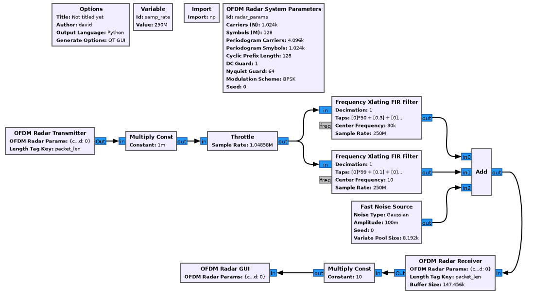
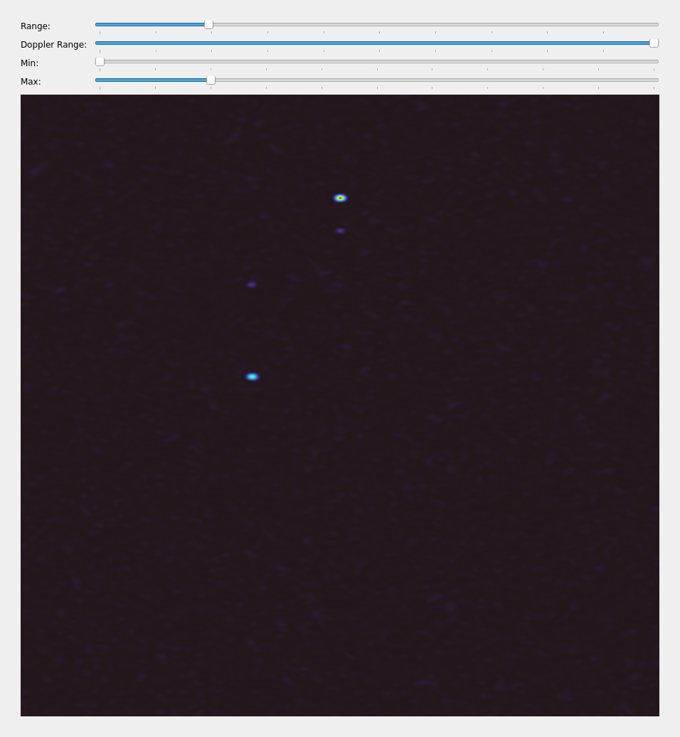
Launch ofdmradar_test example from gr-ofdmradar examples directory.
This simulates four radar targets.
Hardware testing (ZCU102/AD9081)
Open ofdmradar_ad9081.grc flowgraph in gr-ofdmradar examples.
Set iio_target variable to ZCU102 IP address.
Warning
Default configuration may violate local RF regulations; verify band allocation and power limits.
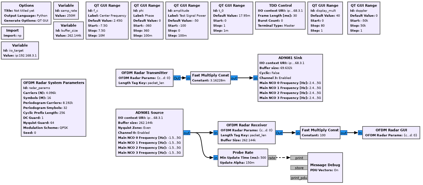
Test result: Successful detection at approximately 35-meter range.
Useful resources
Using the OFDM Radar
System parameters
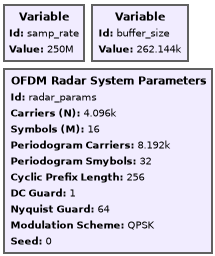
Example parameters:
Complex system sample rate:
f_s = 250 MS/sFFT Size:
N = 4096Frame symbols:
M = 16Cyclic prefix length:
N_CP = 256Nyquist guard carriers:
N_NG = 64
Derived calculations:
Total TX frame length:
L = (N+N_CP)*M = 69,632 samplesFrame duration:
T = L / f_s = 279 microsecondsTime domain resolution (non-oversampled): Approximately 60 centimeters
Doppler resolution (non-oversampled):
f_s / ((N+N_CP)*M) = 3,590 HzTrue system bandwidth:
B = (N - 2*N_NG)/N * f_s = 242.2 MHzProcessing gain:
G = 10 * log10(N * M) ≈ 48 dBMaximum unambiguous distance:
d = N_CP*c / (4*f_s) ≈ 77 meters
Flowgraph parameters
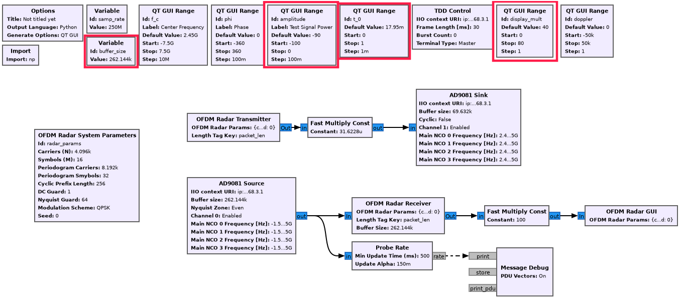
buffer_size
Specifies samples the receiver accepts per frame. Should equal or exceed
frame length L. Controls IIO buffer alignment.
amplitude
Controls transmit power via pre-multiplication. Due to processing gain, required transmit power may be low.
t_0
TDD engine offset between transmission start and recording start. Requires calibration for accurate range determination.
display_mult
Post-processing scaling for return signal intensity visualization. Does NOT affect receiver sensitivity.
Visualization parameters
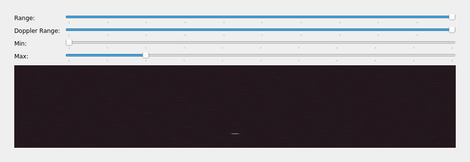
Range Slider
Controls displayed range; functions as inverted zoom (left movement = zoomed range view).
Doppler Range Slider
Reduces displayed doppler ranges similarly.
min/max Value Sliders
Map energy values to visualization using mapping function:
mapv(x) = (x - minV) / (maxV - minV)
return max(min(x, 1.0), 0.0)
Processing pipeline:
Calculate energy from complex 2D matrix (range × doppler)
Apply mapping function with min/max scaling
Pass through turbo colormap
Display on screen
System deep dive
Overview
This section covers system architecture from transceiver through signal processing:
Transceiver/RF ADC/DAC (AD9081)
Hardware/HDL implementation
Linux drivers
gr-ofdmradar signal processing blocks
ZCU102/AD9081 platform
The AD9081 is a 4-channel RF DAC/ADC in single package.
Key features:
Multi-chip synchronization support
JESD 204B/C data interface
8+8 SERDES lanes (RX+TX)
Note
ZCU102 transceivers maximum speed is ~15 Gbps, so only JESD 204B operation is available (not 204C).
Problem statement
Pulse Radar Time-of-Flight Challenge
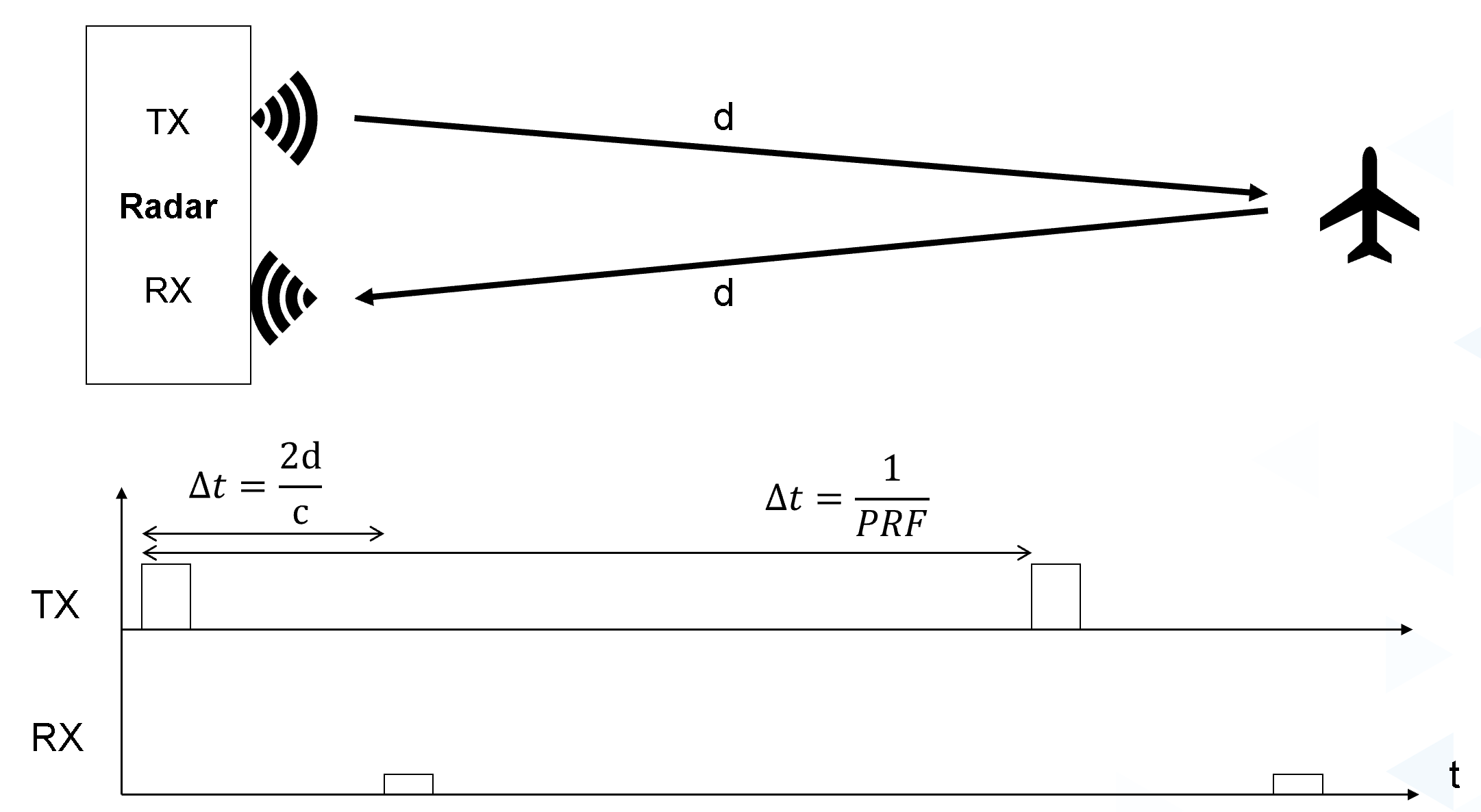
Monostatic radar requires known, fixed timing relationship between transmit and receive to calculate distance via time-of-flight measurement.
Data Rate Bottleneck
Default ZCU102/AD9081 configuration:
Active channels: 4 RX + 4 TX @ 250 MS/s
Sample format: 32-bit complex (16+16 bit)
Data rate per direction:
4 × 250e6 MS/s × 32 bit/sample = 32 Gbps
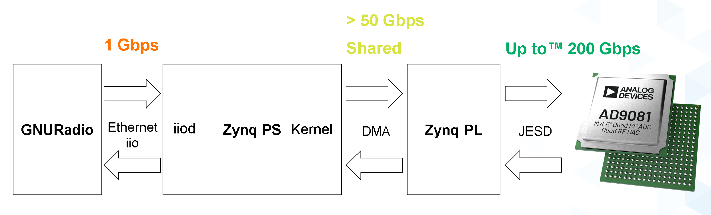
System link limitations:
Memory links: Can handle rates
FPGA: Can handle rates
Processing system: Cannot handle rates
Gigabit Ethernet: Cannot handle rates
IIO Buffer Guarantees
Provided:
Samples within single buffer play as continuous stream
Buffers maintain order (no reordering)
Problem: Without modifications, RX/TX timing relationship is random.
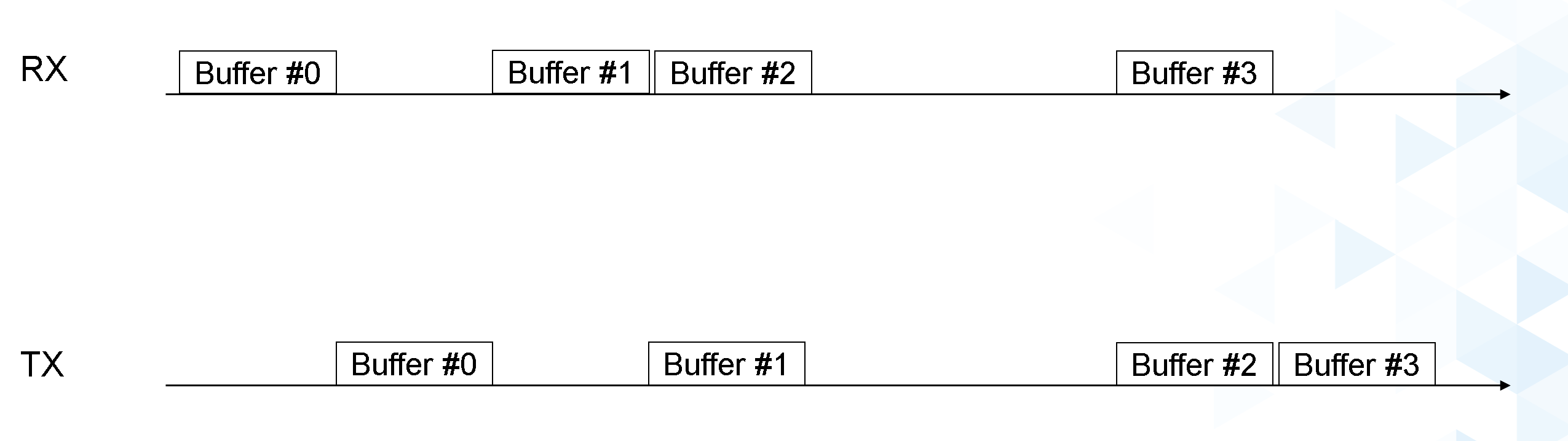
Default scenario: RX and TX buffers sample independently with unpredictable spacing.
Solution: Time Division Duplexing with Data Offload
Hardware-controlled windowing of transmit/receive signals at predetermined times (oscilloscope-like triggering).
Result:
Reduced data rates in controlled manner
Known timing relationships between RX/TX
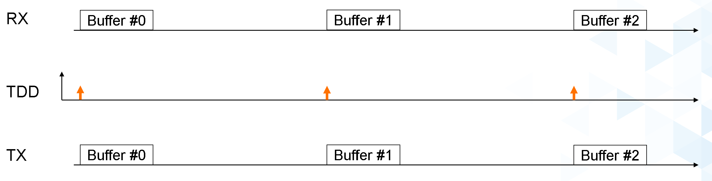
The HDL
HDL changes are in a development branch: Yamakaja/hdl data_offload branch.
TDD (Time Division Duplexing) Core
Originally developed for AD9361 transceiver family. See AXI TDD.
The AXI_TDD wrapper exposes TDD IP core as standalone module. All channels function independently.
Data Offload Engine
Acts as glorified FIFO triggered by TDD engine for sampling data streams.
Key features:
Multiple configuration options
Synchronization modes for waiting state
Triggered operation (register write or external signal)
See Data Offload README.
Integration Architecture
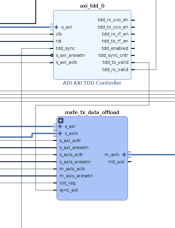
Figure 11 AD9081 ZCU102 block diagram with TDD and data offload
Signal flow:
tdd_tx_valid→ TX data offload external sync inputsync_extsignal triggers data offloadExternal sync signal relevance limited to initial waiting phase
Can transition LOW immediately after trigger
TX Data Path
Once triggered:
Data offload fills internal buffer
Buffer size must be integer multiple of IIO buffer size
Buffer plays back to upack core
Unpacker deinterleaves packed samples into parallel bus
Output: 2×16 bit per complex channel @ 128-bit, 250 MHz
RX Data Path Complexity
Challenge: CPACK core packing format timing asynchrony with TDD sync signal.
Problem scenario:
Single active channel from four-channel configuration
CPACK output valid only once per four samples
CPACK position relative to sync arrival = apparent random shift (0-3 samples)
Current solution: Reset CPACK with every sync signal (not optimal but least invasive approach).
JESD Configuration Detail
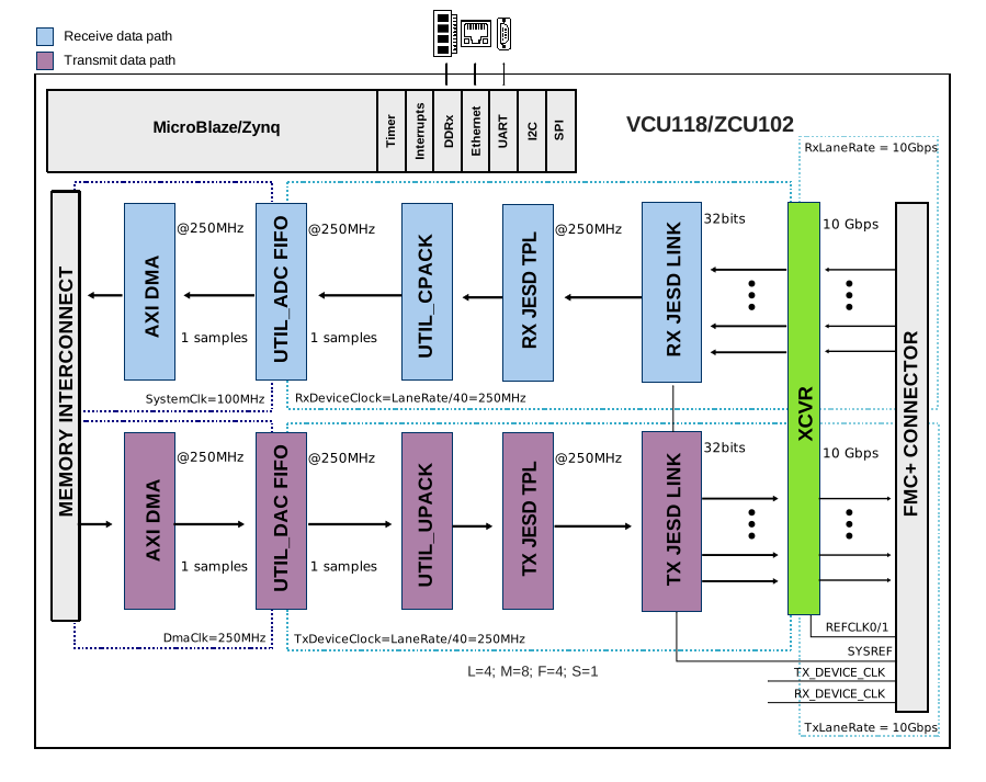
Datapath illustration with M=8, L=4 configuration. UTIL_DACFIFO and UTIL_ADCFIFO replaced by data offloads in actual implementation.
Linux drivers
Two primary drivers:
Data Offload Driver
TDD Driver
Data Offload Driver
Location: drivers/misc/adi-axi-data-offload.c
Primary functions:
Configure data offload registers from device tree values
Provide debugfs runtime register modification interface
Device tree configuration: adi,axi-data-offload.yaml
Integration with DDS driver at cf_axi_dds.c handles cyclic/oneshot operation via data offload.
Use case for repeated radar waveform transmission:
Data offload cyclic mode with synchronization enabled
Waits for sync signal before each iteration
Allows single buffer load with multiple replay iterations
TDD Driver
Location: drivers/iio/adc/cf_axi_tdd.c
Features:
Static configuration via device tree attributes
IIO device interface for runtime control
TDD Register Access example:
iio:device2: axi-core-tdd
4 channels found:
  data1 (output/input): 6 channel-specific attributes
    - dp_off_ms
    - dp_on_ms
    - off_ms
    - on_ms
    - vco_off_ms
    - vco_on_ms
  data0 (output/input): 6 channel-specific attributes
    - [Same attributes as data1]

10 device-specific attributes:
  - burst_count
  - counter_int
  - dma_gateing_mode (options: rx_tx, rx_only, tx_only, none)
  - en
  - en_mode (options: rx_tx, rx_only, tx_only)
  - frame_length_ms
  - secondary
  - sync_terminal_type
  - direct_reg_access (debug)
GNU Radio integration
Two component categories:
Hardware Control Blocks (gr-iio in-tree)
AD9081 Source/Sink
TDD Engine Control
Signal Processing Blocks (gr-ofdmradar)
Hardware-independent OFDM radar processing
Direction of arrival (DoA) blocks
gnuradio/gr-iio blocks
Operational Model: Bursty Data Assumption
Working with bursts where one burst = one IIO buffer.
Burst indication: Packet length tags marking buffer boundaries.
Tag format example:
[... x-2, x-1, x0, x1, x2, x3, x4, x5, x6, x7, x8, x9, x10, x11, x12, ...]
        ^                                       ^
        |{packet_len: 10}              |{packet_len: 10}
Packet length tags are redundant for same-size IIO buffers but enable compatibility with variable-size streams.
AD9081 Sink Block: If packet length tag name populated, sink enforces correct tagging and aborts flowgraph on errors.
Common Block Attributes
Shared parameters:
IIO context URI
IIO buffer size
Packet length tag name
NCO attributes
Source-specific:
Nyquist Zone (Odd/Even)
Programmable hardware FIR filter file
Sink-specific:
Cyclic Mode
AD9081 Sink Block Configuration
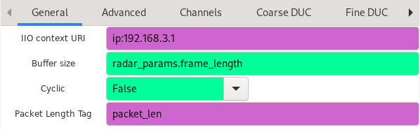
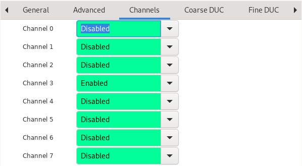
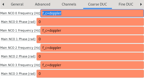
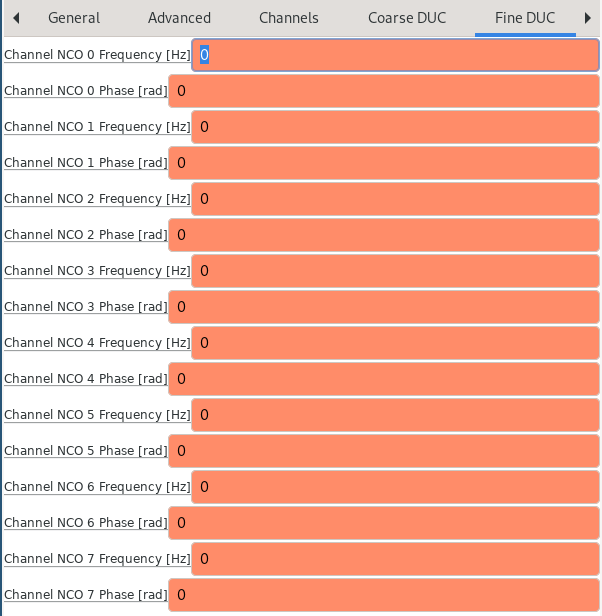
AD9081 Source Block Configuration
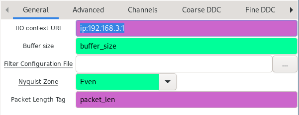
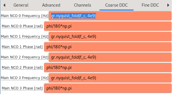
Frequency calculation uses gr.nyquist_fold() function to calculate NCO
frequencies accounting for aliasing and spectral inversion.
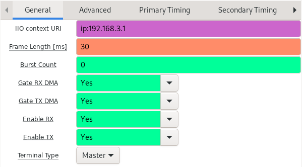
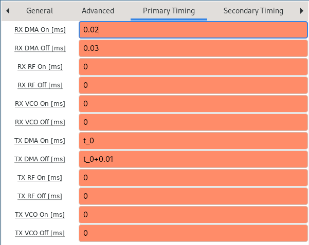
TDD Control Block
Stream IO: None
Purpose: Convenient access to underlying IIO attributes.
gr-ofdmradar signal processing blocks
Block categories:
OFDM Radar blocks (TX, RX, GUI)
Direction of Arrival (DoA) blocks
OFDM Radar System Parameters Block
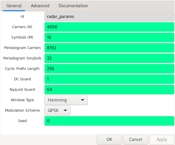
Purpose: Store shared system parameters for TX, RX, GUI blocks.
OFDM Radar Transmitter Block

Inputs: System parameters, length tag key.
Output: Full OFDM radar frame, length-tagged for AD9081 sink compatibility.
OFDM Radar Receiver Block
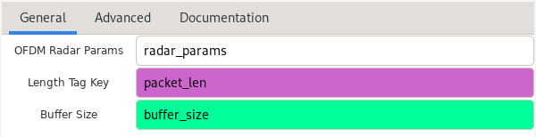
Inputs: System parameters, length tag key, buffer size.
buffer_size parameter:
Specifies expected samples per OFDM frame
Actual processing determined by OFDM parameters
Allows discarding additional samples for IIO buffer alignment
Discarded samples:
buffer_size - radar_params.frame_length
OFDM Radar GUI Block

Inputs: OFDM radar parameters, GUI hint.
Purpose: Real-time radar display with range/doppler visualization.
Direction of Arrival (DoA) blocks
DoA Autocorrelator Block

Purpose: Compute correlation matrices from multi-channel receiver data.
DoA Calibration Block
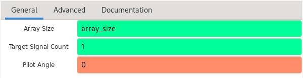
Purpose: Calibrate antenna array responses.
DoA MUSIC Estimator Block
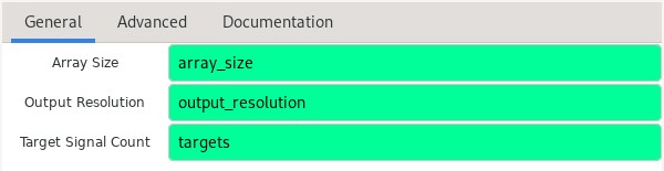
Algorithm: MUSIC (Multiple Signal Classification) for direction estimation.
DoA ESPRIT Estimator Block
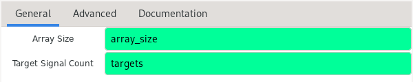
Algorithm: ESPRIT (Estimation of Signal Parameters via Rotational Invariance Techniques).
DoA Block Assumptions
Implicit assumptions:
Linear antenna array topology
Lambda/2 carrier wavelength spacing
Primary parameters:
Number of expected targets
Number of receiver channels