EVAL-CN0415-ARDZ Shield
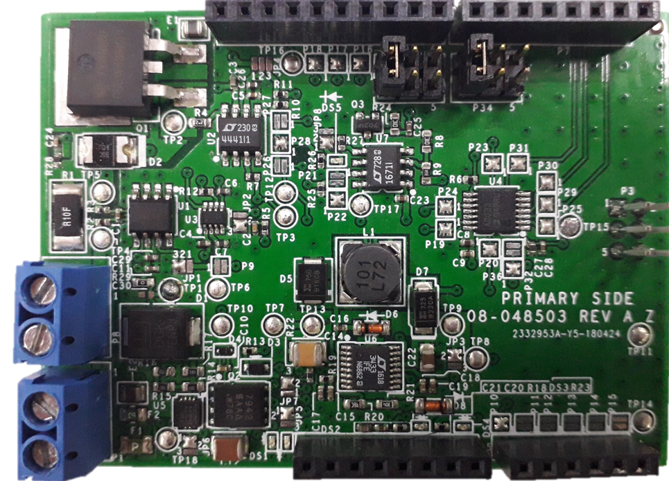
CN0415 is a robust pulse-width modulation (PWM) solenoid driver circuit in an Arduino shield form factor. Target applications include motion control, latches, clamps, brakes, clutches, proportional gas valves, proportional liquid valves, and other industrial applications. The circuit provides accurate, closed-loop current control in 2-state solenoid applications, allowing low-voltage solenoids to be used over a wide range of supply voltages, tolerating overvoltage and under voltage transient conditions caused by cold-cranking and load dump conditions.
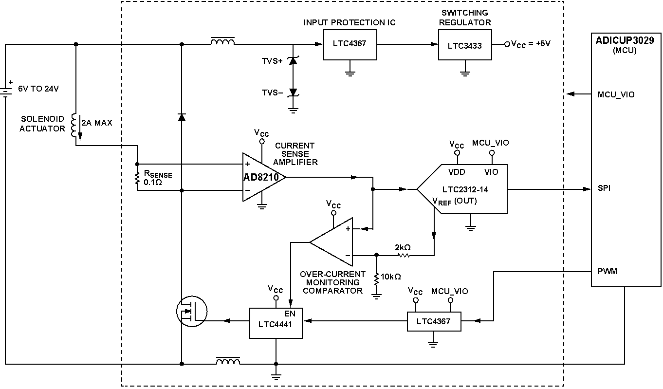
Simplified functional block diagram
The simplified circuit diagram shown in figure 1 is a robust solution for accurately and efficiently driving proportional and two-state solenoid actuators. Applications include motion control, latches, clamps, brakes, clutches, proportional gas valves, and proportional liquid valves. The circuit provides accurate, closed-loop current control in 2-state solenoid applications, allowing low-voltage solenoids to be used over a wide range of supply voltages. Initial pull-in current, pull-in time delay, and hold current are independently adjustable in software, greatly reducing power consumption in applications in which the solenoid is continuously energized.
The circuit provides a complete driver solution in proportional valve applications; pulse-width modulation (PWM) duty cycle and frequency can be directly controlled by an external PID controller, and a dither current with programmable frequency and amplitude can be enabled in order to reduce mechanical stiction.
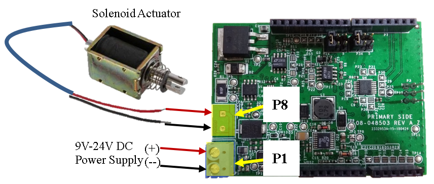
Power Supply Requirements
The CN0415 requires a power supply voltage between 6V and 24V. The current requirement can be as high as 3A, depending on the solenoid’s DC resistance.
Solenoid Requirements
A Deltrol model TAU0730T-02 12V solenoid is provided with the CN0415 as an example. In general, CN0415 will drive any solenoid actuator with an operating voltage of 24V or less and an operating current of 3A.
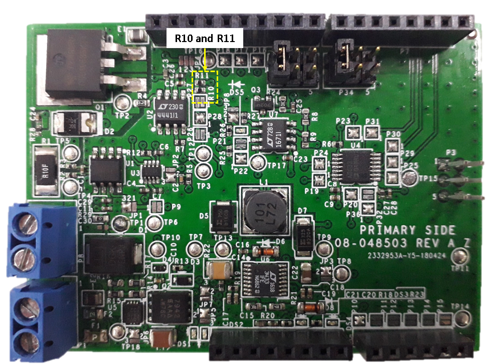
When driving low voltage solenoids from a high input supply voltage, solenoid current can be limited in software and by adjusting the overcurrent latchoff threshold set by R10-11.
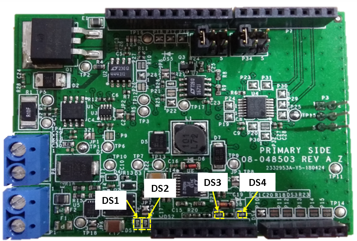
LED Indicators
LED Indicator |
Initial State |
Description |
|---|---|---|
DS1 |
ON |
Indicates that the LT4367 supply input voltage supply range |
are within its limit |
||
DS2 |
OFF |
Indicates that the LT4367 did detectany fault issue from the input source. |
Turns on if the input range is in over voltage range |
||
( where in the limit is currently set at 24V) |
||
DS3 |
ON |
Indicates a +3.3V voltage source from the arduino MCU board |
DS4 |
ON |
Indicates a +VCC voltage source going to the system which either |
comes from a +3.3V of the Arduino MCU or a +5V output voltage |
||
supply from LT3433 which is set by JP3 |
||
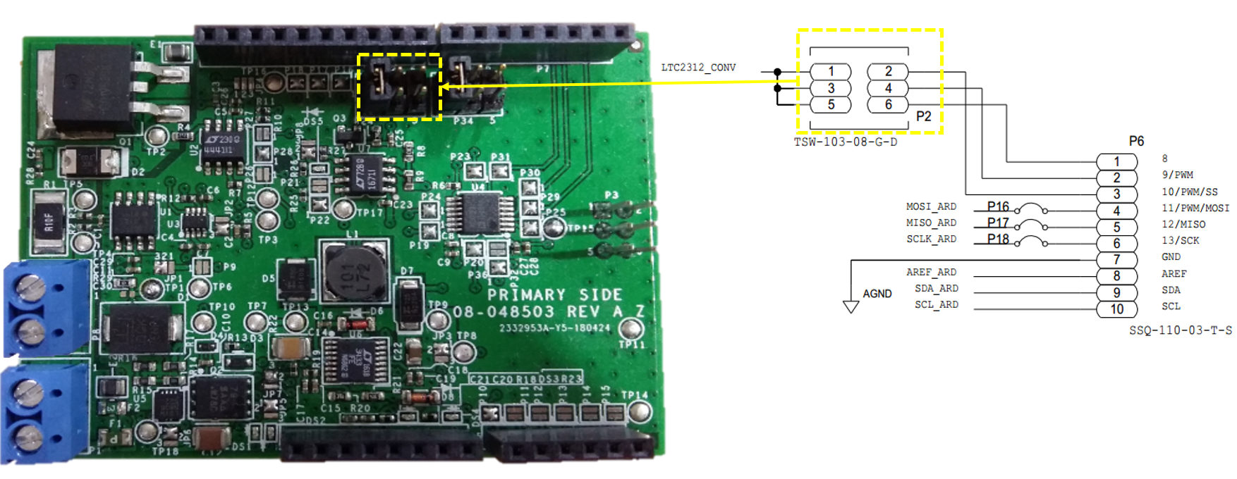
ADC Chip Select Jumper Pin Selection
The chip select jumper settings allows the user to stack up multiple boards to the microcontroller board when using SPI digital communication protocol.
Jumper Name |
Position |
Description |
|---|---|---|
P2 |
1 and 2 |
set the chip select to P6-3 of the Arduino MCU GPIO pin terminal |
3 and 4 |
set the chip select to P6-2 of the Arduino MCU GPIO pin terminal |
|
5 and 6 |
set the chip select to P6-1 of the Arduino MCU GPIO pin terminal |
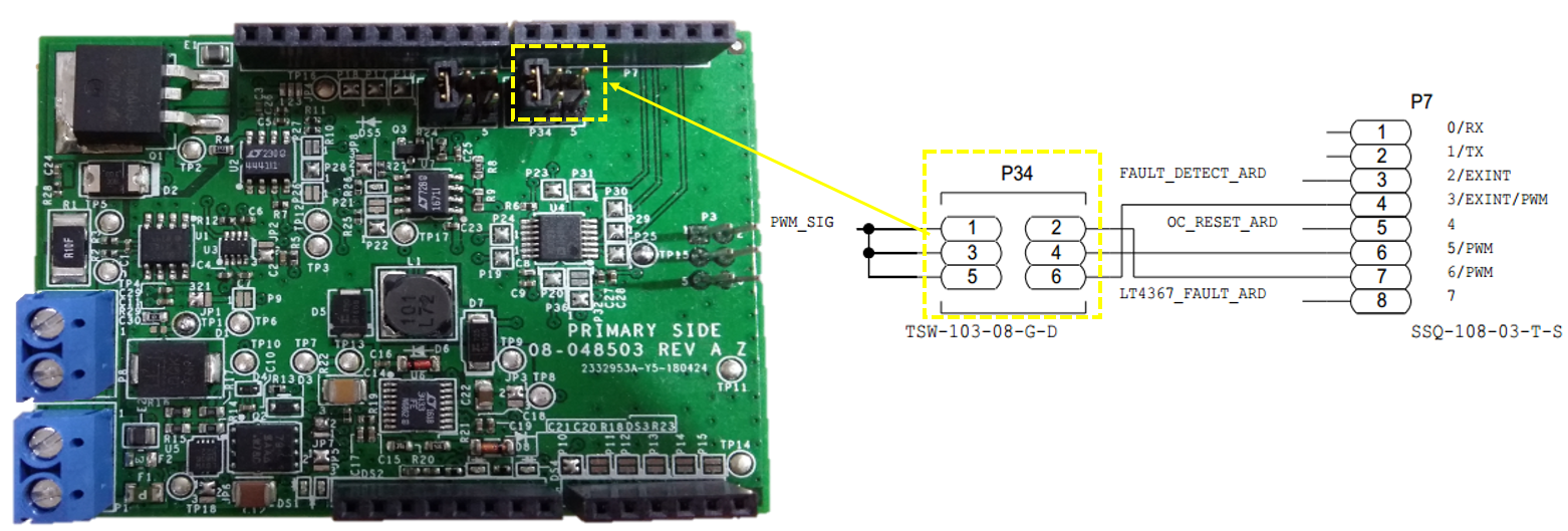
PWM Jumper Pin Selection
The PWM jumper pin selection allows the user to choose from the GPIO pins of the microcontroller to generate excitation rectangular pulse which goes to the N-Channel Mosfet gate driver.
Jumper Name |
Position |
Description |
|---|---|---|
P34 |
1 and 2 |
set the PWM output from P7-7 of the Arduino MCU GPIO pin terminal |
3 and 4 |
set the PWM output from P7-6 of the Arduino MCU GPIO pin terminal |
|
5 and 6 |
set the PWM output from P7-4 of the Arduino MCU GPIO pin terminal |
Other Configuration Options (Default Positions Indicated)
Board Function |
Jumper Name |
Position |
Description |
|---|---|---|---|
Current Monitor Offset |
JP1 |
1 and 2 |
ADC Midscale (2.048V) |
2 and 3(Default) |
0V |
||
ADC Selection |
JP2 |
1 and 2 |
Current Monitor to Arduino ADC |
2 and 3(Default) |
Current Monitor to onboard ADC |
||
Vcc Supply Selection |
JP3 |
1 and 2(Default) |
Vcc supply from +5V from on board LDO |
2 and 3 |
Vcc supply from +3.3V Arduino pin |
||
Switching Regulator Burst-Mode Selection |
JP5 |
1 and 2(Default) |
Disabled Burst-Mode functionality |
2 and 3 |
Enabled Burst-Mode functionality |
||
Hardware Fault Detection on Power Supply Input |
P6 |
1 and 2(Default) |
Enable hardware fault detection via LED indicator |
2 and 3 |
Disable hardware fault detection |
||
Hardware Fault Detection on Switching Regulator Output |
P7 |
1 and 2 |
Enable hardware fault detection via LED indicator |
2 and 3(Default) |
Disable hardware fault detection |
||
Overcurrent latch off |
JP8 |
1 and 2(Default) |
latch off enabled |
2 and 3 |
latch off disabled |
||
Arduino ADC channel select |
P10-P15 |
P10(Default) |
Select Arduino analog input for current monitor. |
OC/UC select |
P21-P22 |
P22(Default) |
Select fault polarity(Overcurrent or undercurrent) |
Logic Signal Control |
P32 and P36 |
P32 |
Disable on Fault |
P36 (Default) |
Always Enabled |
||
Output Enable |
P26-P28 |
P26 |
Always Enabled |
P27 |
GPIO/Software control |
||
P28(Default) |
Disable on Fault |
||
Arduino Vref |
P9 |
P9(Open) |
Short to set Arduino Vref to 4.096V |
ADC CS |
P2 |
1 and 2(Default) |
GPIO to use for ADC CS |
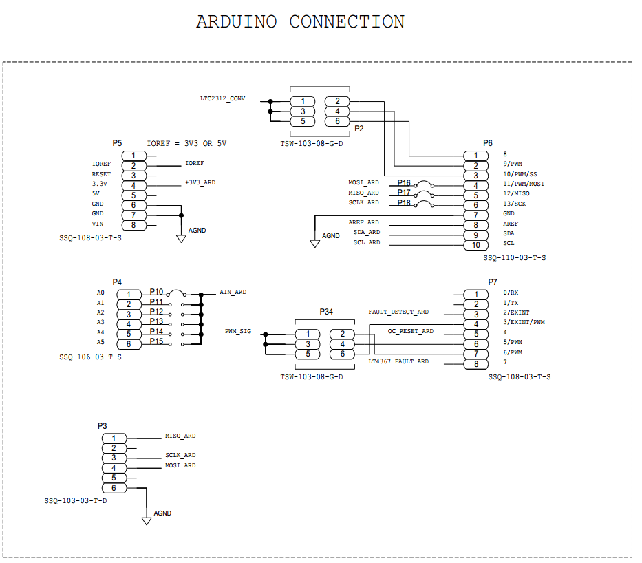
Arduino Interface
The EVAL-CN0415-ARDZ is compatible with the EVAL-ADICUP3029 platform. Because the ADICUP3029 is an Arduino form factor compatible development board, many other equivalent Arduino form factor development board can also be used simply by writing custom code. Below is the pinout of the custom connector of the EVAL-CN0415-ARDZ eval board.
Software
The ADuCM3029_demo_cn0415 provides a solution for controlling and monitoring solenoid actuator current, using an EVAL-CN0415-ARDZ shield installed on an EVAL-ADICUP3029 base board. The user interface is implemented as a command line interface (CLI) through a serial UART connection. The project is created using CrossCore Embedded Studio and GNU ARM compiler.
Schematic, PCB Layout, Bill of Materials
Download
EVAL-CN0415-ARDZ Design & Integration Files
Schematics
Bill of Materials
Gerber Files
Assembly Files
More Information and Useful Links
Registration
Tip
Receive software update notifications, documentation updates, view the latest videos, and more when you register your hardware. Register to receive all these great benefits and more!
End of Document