PLC Arduino Shield Output Demo
The ADuCM3029_demo_cn0418 project provides a solution to control a PLC or DCS output system using the EVAL-CN0418-ARDZ and the EVAL-ADICUP3029. It uses a DAC with 4 channels that can be configured as either voltage or current output and is compatible with HART modem output to enable HART communication on any channel. It has a 32kb EEPROM memory that can also be used to identify the board and is controlled via a command line interface (CLI).
General Description/Overview
The EVAL-CN0418-ARDZ is an Arduino compatible shield includes a AD5755-1 (quad channel voltage and current output DAC with dynamic power control) and the AD5700-1 HART modem, to give a completely isolated multiplexed HART analog output solution.
The ADuCM3029_demo_cn0418 application uses different software modules to deliver a CLI interface that can be used to set any channel range or output and transmit and receive HART messages on any of those channels. It uses SPI to communicate with the AD5755-1, to read and write its registers. The channle code and range registers can be set as well as the RSET register. It can function both in voltage and current mode.
The current mode is used with the AD5700-1 HART modem to transmit and receive HART messages. The application can send command zero and then receive and interpret the result. The receiving is done asynchronous through the use of GPIO group interrupts featured by the ADuCM3029. The maximum baudrate of the HART communication is 1200 and is implemented by a software UART. It transmits and receives data bytes of 8 bits with one stop bit and one parity bit, using odd parity.
The CLI is implemented using the hardware UART module in the ADuCM3029 and can work up 115200 baudrate.
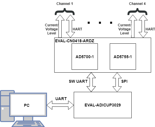
Demo Requirements
The following is a list of items needed in order to replicate this demo.
Hardware
EVAL-ADICUP3029
EVAL-CN0418-ARDZ
Mirco USB to USB cable
PC or Laptop with a USB port
24V source
Software
ADuCM3029_demo_cn0418 software
CrossCore Embedded Studio (2.8.0 or higher)
ADuCM302x DFP (3.2.0 or higher)
ADICUP3029 BSP (1.1.0 or higher)
Serial Terminal Program
Such as Putty or Tera Term
Setting up the Hardware
Connect EVAL-CN0418-ARDZ to the EVAL-ADICUP3029.
Set the jumpers into the position shown below. This is the standard position and only works for one board systems.
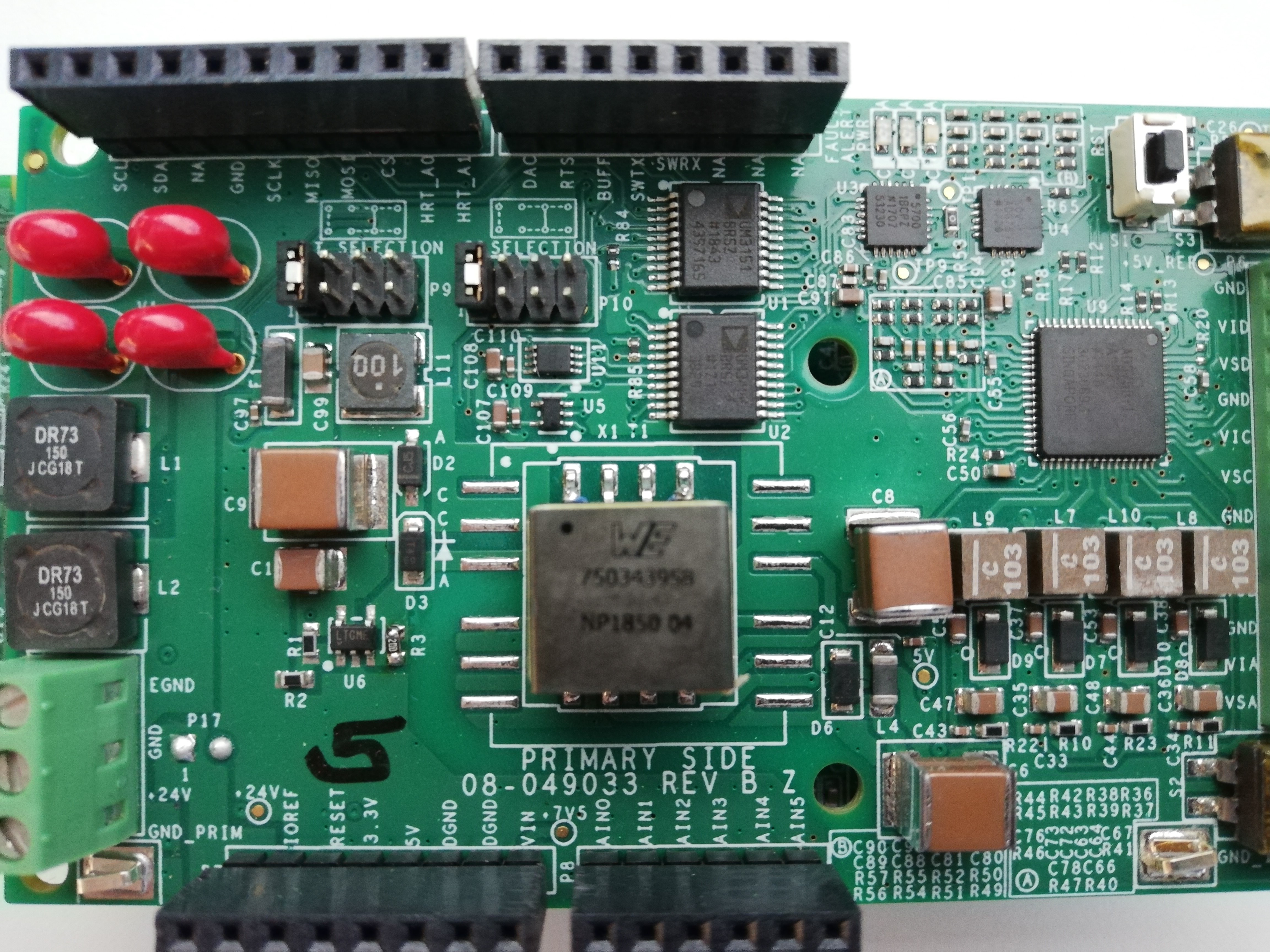
Connect a micro-USB cable to P10 connector of the EVAL-ADICUP3029 and connect it to a computer.
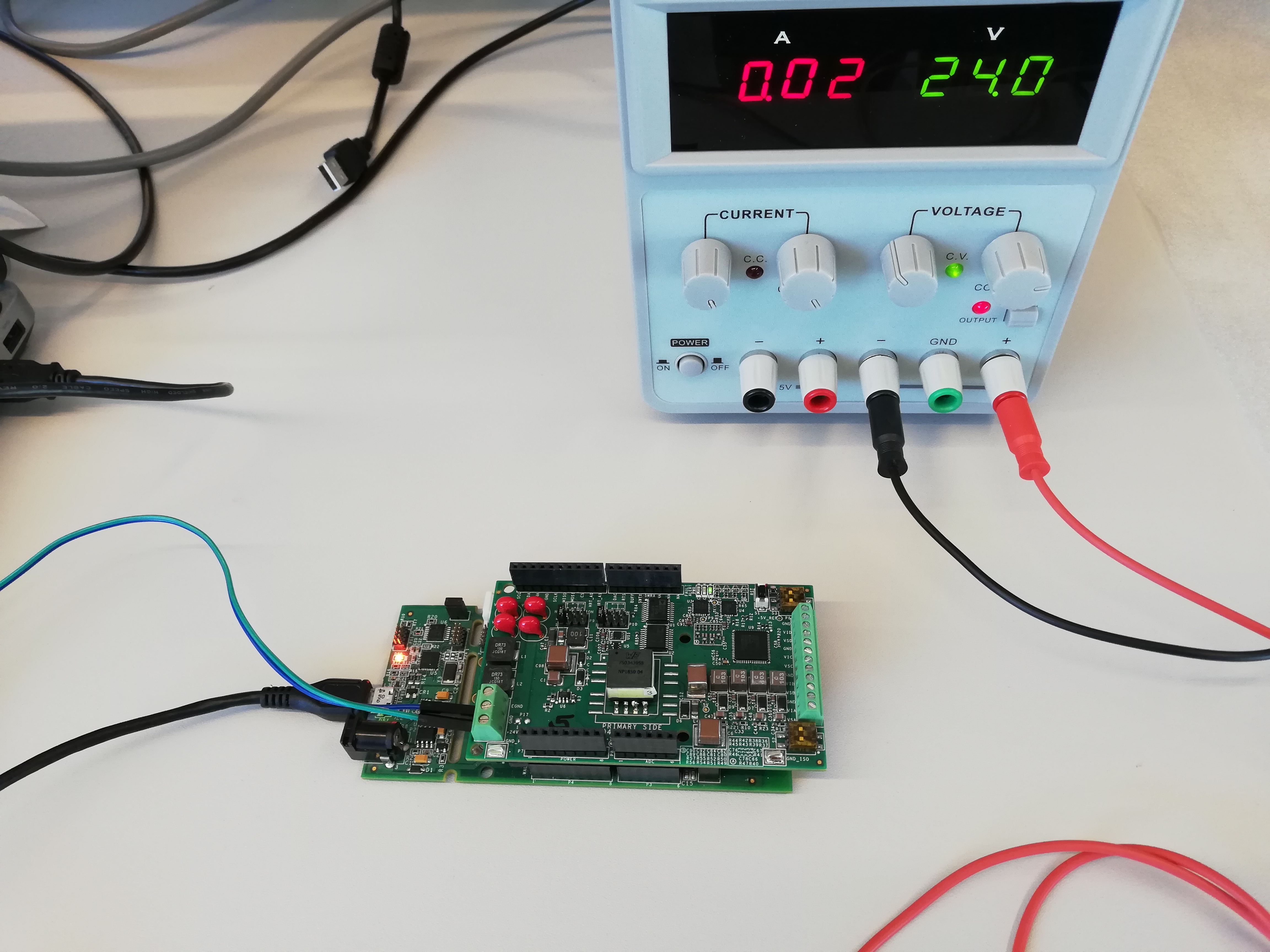
Connect the 24V power source to the P1 connector with the ground wire to pin 2 and 24V wire to pin 3. The final setup should look similar to the picture below.
Configuring the Software
The software needs no configuration beyond the CLI UART baudrate, and HART UART parity and number of bits. These can be accessed in the ADuCM3029_demo_cn0418.c file in the main function, but usually the default values work best.
Outputting Data
Serial Terminal Output
Serial Terminal Setup
A serial terminal is an application that runs on a PC or laptop that is used to display data and interact with a connected device (including many of the Circuits from the Lab reference designs). The device’s UART peripheral is most often connected to a UART to USB interface IC, which appears as a traditional COM port on the host PC/ laptop. (Traditionally, the device’s UART port would have been connected to an RS-232 line driver / receiver and connected to the PC via a 9-pin or 25-pin serial port.) There are many open-source applications, and while there are many choices, typically we use one of the following:
Before continuing, please make sure you download and install one of the above programs.
There are several parameters on all serial terminal programs that must be setup properly in order for the PC and the connected device to communicate. Below are the common settings that must match on both the PC side and the connected UART device.
COM Port - This is the physical connection made to your PC or Laptop, typically made through a USB cable but can be any serial communications cable. You can determine the COM port assigned to your device by visiting the device manager on your computer. Another method for identifying which COM port is associated with a USB-based device is to look at which COM ports are present before plugging in your device, then plug in your device, and look for a new COM port.
Baud Rate - This is the speed at which data is being transferred from the connected device to your PC. These parameters must be the same on both devices or data will be corrupted. The default setting for most of the reference designs is 115200.
Data Bits - The number of data bits per transfer. Typically UART transmits ASCII codes back to the serial port so by default this is almost always set to 8-Bits.
Stop Bits - The number of “stop” conditions per transmission. This is usually set to 1, but can be set to 2 for redundancy.
Parity - Is a way to check for errors during the UART transmission. Unless otherwise specified, set parity to “none”.
Flow Control - Is a way to ensure that data between fast and slow devices on the same UART bus is not lost during transmission. This is typically not implemented in a simple system, and unless otherwise specified, set to “none”.
In many instances there are other options that each of the different serial terminal applications provide, such as local line echo or local line editing, and features like this can be turned on or off depending on your preferences.
Example setup using PuTTY
Plug in your connected device using a USB cable or other serial cable.
Wait for the device driver of the connected device to install on your PC or Laptop.
Open your device manager, and find out which COM port was assigned to your device.
Open up your serial terminal program (PuTTY for this example).
Click on the serial configuration tab or window, and input the settings to match the requirements of your connected device. The default baud rate for most of the reference designs is 115200. Make sure that you use the correct baud rate for your application.
Ensure you click on the checkboxes for Implicit CR in every LF and Implicit LF in every CF.
Ensure that local echo and line editing are enabled, so that you can see what you type and are able to correct mistakes. (Some devices may echo typed characters - if so, you will see each typed character twice. If this happens, turn off local echo.)
Tip
If you see nothing in the serial terminal, try hitting the reset button on the embedded development board.
Available Commands
Typing help or h after initial calibration sequence will display the list of commands and their short versions. Bellow is the short command list:
Command |
Description |
|---|---|
General commands |
|
h |
Display available commands. |
stts |
Display parameters of the application. |
DAC commands |
|
dsr |
Set range of a channel. <chan> = channel to be set. Available channel options are: cha, chb, chc, chd. <range> = chosen range for the channel. Available options are: - r05v = range from 0 to 5 volts; - r010v = range from 0 to 10 volts; - rmp5v = range form -5 to +5 volts; - rmp10v = range from -10 to +10 volts; - r420ma = range from 4 to 20 mili-amperes; - r020ma = range from 0 to 20 mili-amperes; - r024ma = range from 0 to 24 mili-amperes. |
dsv |
Set voltage output on a channel. Only works if the channel is set to a voltage range. <chan> = channel to update. Available channel options are: cha, chb, chc, chd. <voltage> = voltage level expressed in volts. Use decimal point for fractional values. |
dsc |
Set current output on a channel. Only works if the channel is set to a current range. <chan> = channel to update. Available channel options are: cha, chb, chc, chd. <current> = current level expressed in amperes. Use decimal point for fractional values. |
dsx |
Set output on a channel. Works independent of channel range. <chan> = channel to update. Available channel options are: cha, chb, chc, chd. <code> = 16-bit output code for the channel. |