ACE Software Guide
The ACE software is available here.
Installation Guide
The EVAL-AD7173-8ARDZ evaluation kit includes a link to the software that needs to be installed before using the EVAL-AD7173-8ARDZ evaluation board.
Important
The evaluation software and drivers must be installed before connecting both the evaluation board and the SDP-K1 board to the PC. This ensures that the evaluation system is correctly recognized when it is connected to the PC.
Installing the ACE Software
To install the ACE software:
With the SDP board disconnected from the USB port of the PC, download the ACE evaluation software package to start the ACE evaluation software installation.
Click on Download ACE Installer.
Run the installer and follow the instructions to complete the software installation process.
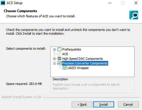
During the installation process, be sure to select Precision Converter Components when prompted and enable the LibIIO Wrapper to ensure that all necessary software components are installed.
Tip
The LibIIO Wrapper must be installed for ACE to detect the connected hardware. If you need to install the LibIIO Wrapper after ACE has been installed, click the ‘Help’ button in the main ACE window. In the ‘ACE Help’ panel that appears expand the ‘Application Resources’ section, and you will find a link to run a local copy of the LibIIO Wrapper Installer.
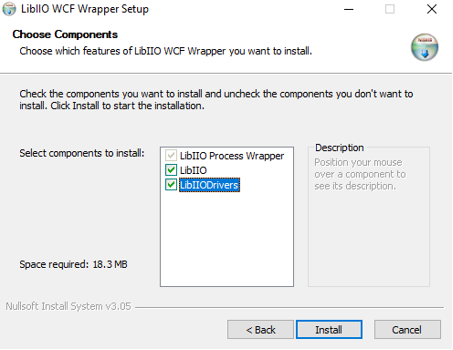
When the following prompt appears, be sure to select LibIIO and LibIIODrivers options, then click Install.
Evaluation Hardware Setup
When the ACE evaluation software installation is complete, take the following steps to set up the SDP-K1 and evaluation board together.
Connect the SDP-K1 and evaluation board using the Arduino headers.
Connect the power supplies configuration.
Connect the USB cable to the SDP-K1.
Open the ACE software.
Software Operation
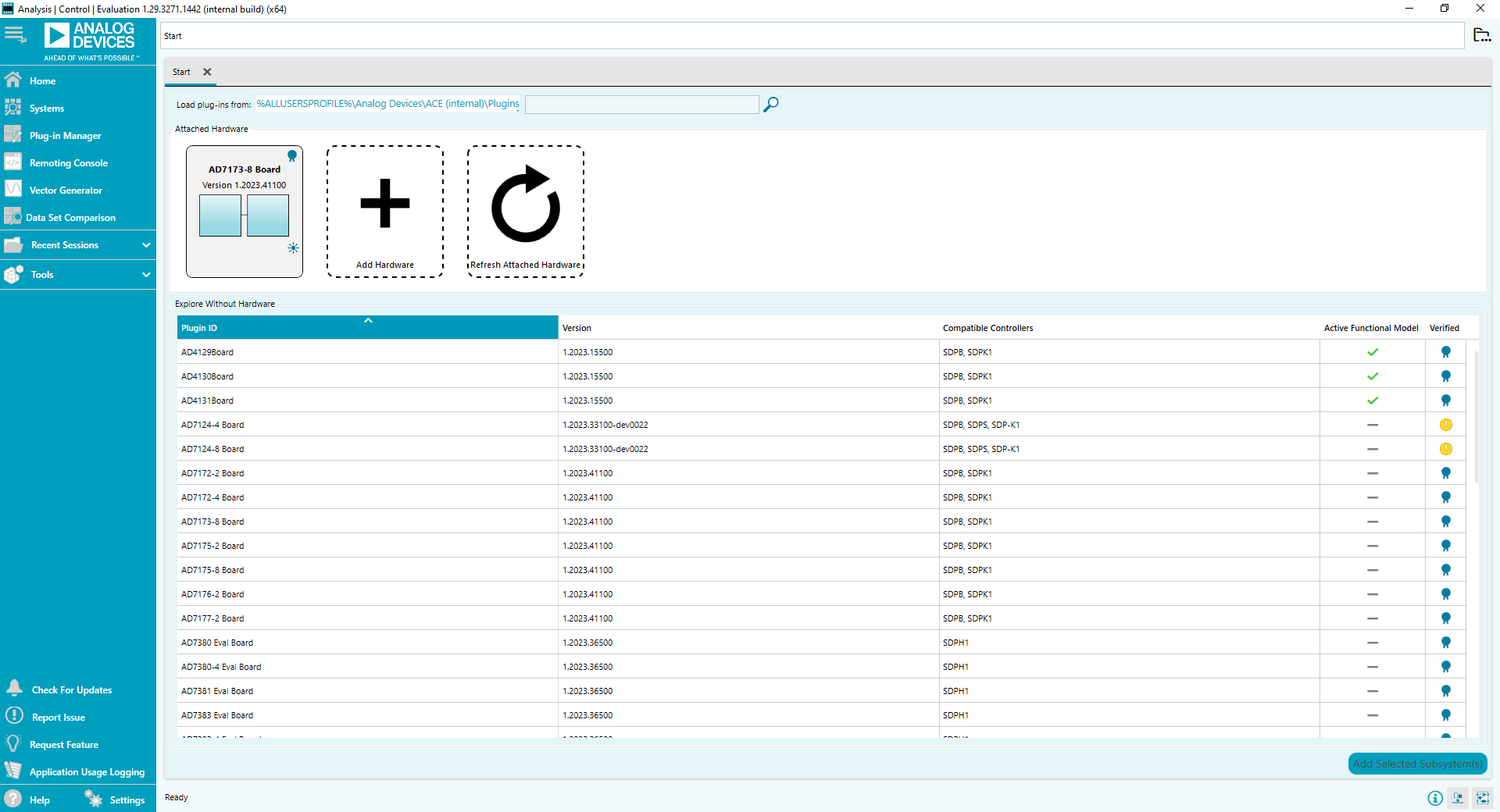
To start the ACE evaluation software, from the Windows Start menu, click Analog Devices > ACE. The software window opens until the software recognizes the AD7173-8 evaluation board. When the software recognizes the board, double-click on the icon in the Start view to open the main window. Make sure that you already have the AD717x-8 plugin in the plugin manager.
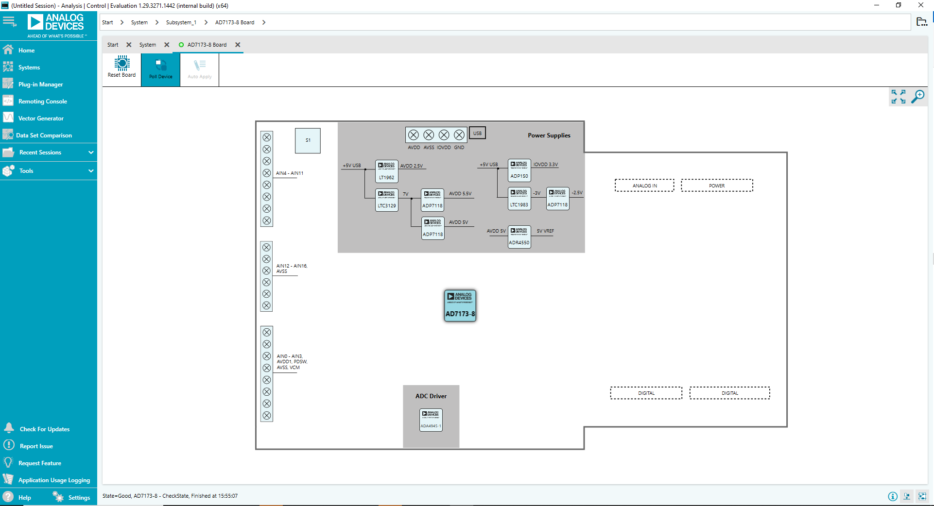
By clicking on the part in the main ACE evaluation software window, the chip view will be opened.
The chip view shows the block diagram of the AD7173-8. This tab allows the user to select inputs, set up the ADC, reset the ADC, and view errors present, as well as configure the device for different demonstration modes. The following sections discuss the different elements on the Chip view of the software window.
Configuration Tab
The Configuration tab shows a block diagram of the AD7173-8. This tab allows the user to select inputs, set up the ADC, reset the ADC, and view errors present, as well as configure the device.
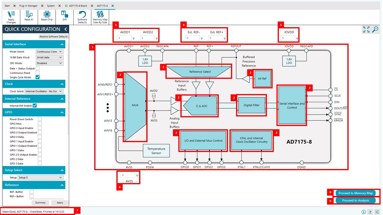
Functional Block Diagram — shows each of the functional blocks within the AD7173-8. Clicking a functional block on this diagram opens the configuration pop-up window for that block.
Configuration Pop-Up Button — each block has a pop-up window which opens a different window to configure the relevant block.
AVDD1 and AVDD2 — external parameters set by the EVAL-AD7173-8ARDZ that must also be entered into the software.
External Reference — the external reference on the EVAL-AD7173-8ARDZ is set to 2.5 V by using an ADR4525. If bypassing the ADR4525 on the board, change the external reference voltage value in the software to ensure correct calculation of results in the Waveform and Histogram tabs in the Waveform Analysis window.
IOVDD — external parameter set by the EVAL-AD7173-8ARDZ that must also be entered into the software.
AVSS — external parameter set by the EVAL-AD7173-8ARDZ that must also be entered into the software.
Status Bar — displays status updates.
Memory Map Button — opens the Memory Map tab.
Waveform Analysis Button — opens the Waveform tab.
Waveform Tab
The Waveform tab can display the different waveforms for voltage input, current input and select the channel. The waveform tab graphs the conversions gathered and processes the data, calculating the peak-to-peak noise, rms noise, and resolution.
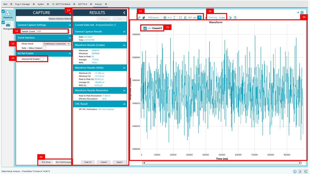
Waveform Graph — shows each successive sample of the ADC output.
Control Toolbar — zoom in on the data in the graph. Change the scales on the graph by typing values into the x-axis and y-axis fields.
Samples — sets the number of samples gathered per batch.
Serial Interface and Internal Reference — sets the ADC mode, enables DATA_STAT and Internal Reference.
Run — click Run Once or Run Continuously to start gathering ADC results. If Run Once is clicked, the ADC returns the number of samples specified by the Samples control. If Run Continuously, the ADC continuously returns samples until stopped by the user. Samples specifies the amounts of samples to be shown on the data graph. This control is unrelated to the ADC mode. Results appear in the waveform graph (10).
Channel Selection — selects which channel/s is displayed on the data waveform. These controls only affect the waveform graphs and have no effect on the channel settings in the ADC register map.
Display Units and Axis Controls — click the Units dropdown box to select whether the data graph displays in units of voltages/amps or codes. This control is independent for each graph.
Results Pane — displays parametric values for the selected display format. The bottom of the RESULTS pane also has buttons that allow the user to import or export sample data.
Histogram Tab
The Histogram tab generates a histogram using the gathered samples and processes the data, calculating the peak-to-peak noise, rms noise, and resolution.
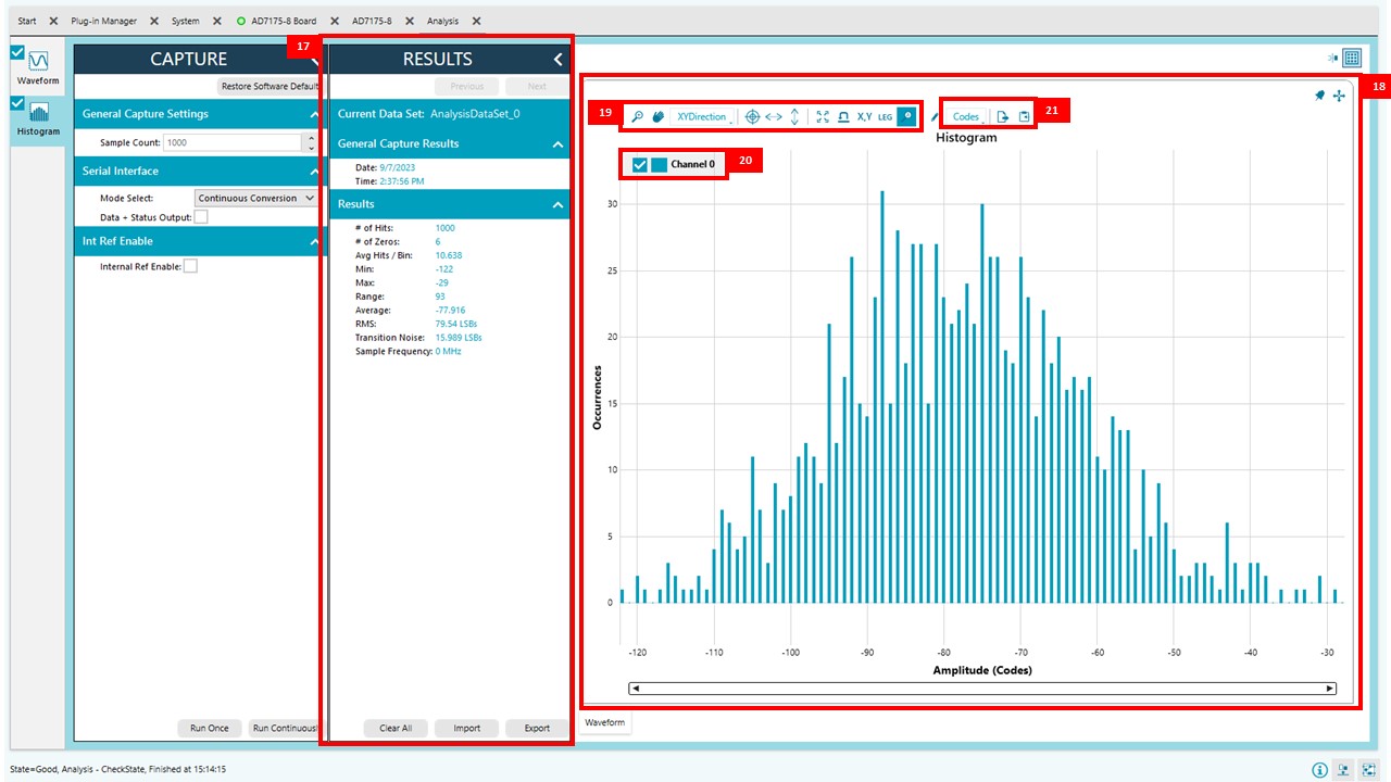
Histogram Graph — shows the number of times each sample of the ADC output occurs.
Control Toolbar — zoom in on the data in the graph.
Channel Selection — selects which channel/s is displayed on the data waveform. These controls only affect the waveform graphs and have no effect on the channel settings in the ADC register map.
Display Units and Axis Controls — click the Units dropdown box to select whether the data graph displays in units of voltages/amps or codes. This control is independent for each graph.
Memory Map
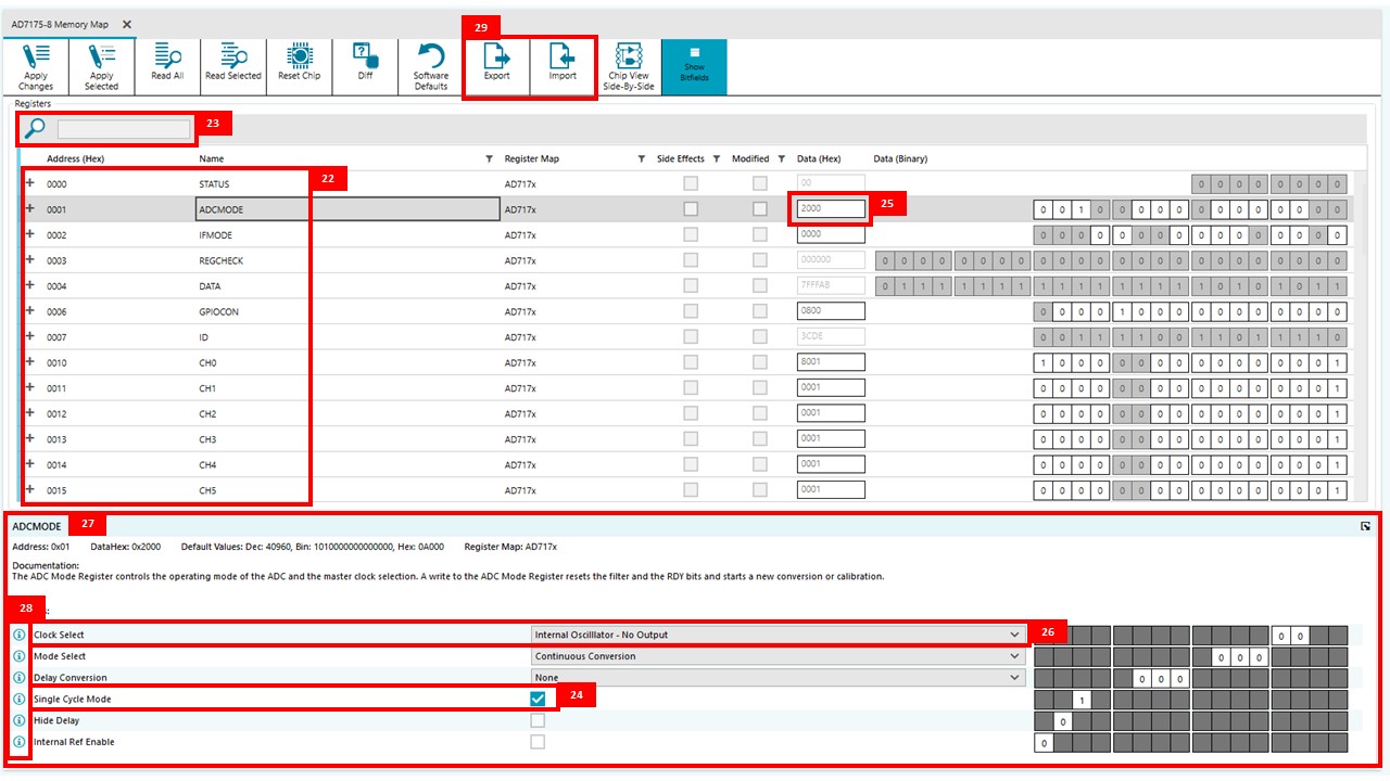
Register Tree — shows the full register map in a tree control. Each register is shown. Clicking the expand button next to each register shows all the bit fields contained within that register.
Register Tree Search — allows the user to search the tree for any register or bit field. Enter a value into this field to filter the register tree.
Register and Bit Field Control — allows the user to change the individual bit of the register selected in the register tree by clicking the bits or by programming the register value directly into the number control field (25). This control also shows all bit fields for the selected register.
Number Control Field — program the register value directly.
Dropdown Box — change bit field values using a dropdown.
Checkbox — select or clear to change bit field values.
Bitfield Documentation — contains the documentation for the register or the bit field selected. This field can be updated by selecting a register or bit field in the register tree or hovering over the register or bit field in the register tree or register control. This documentation will be displayed by clicking the
 button.
Import and Export — save the current register map setting to a file and load the setting from the same file, respectively.