AD-QUADMXFE1-EBZ
Quad-MxFE System Development Platform: Four AD9081 MxFE™ Direct RF Sampling Transceivers, 16Tx/16Rx Channels.
Overview
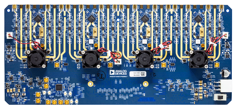
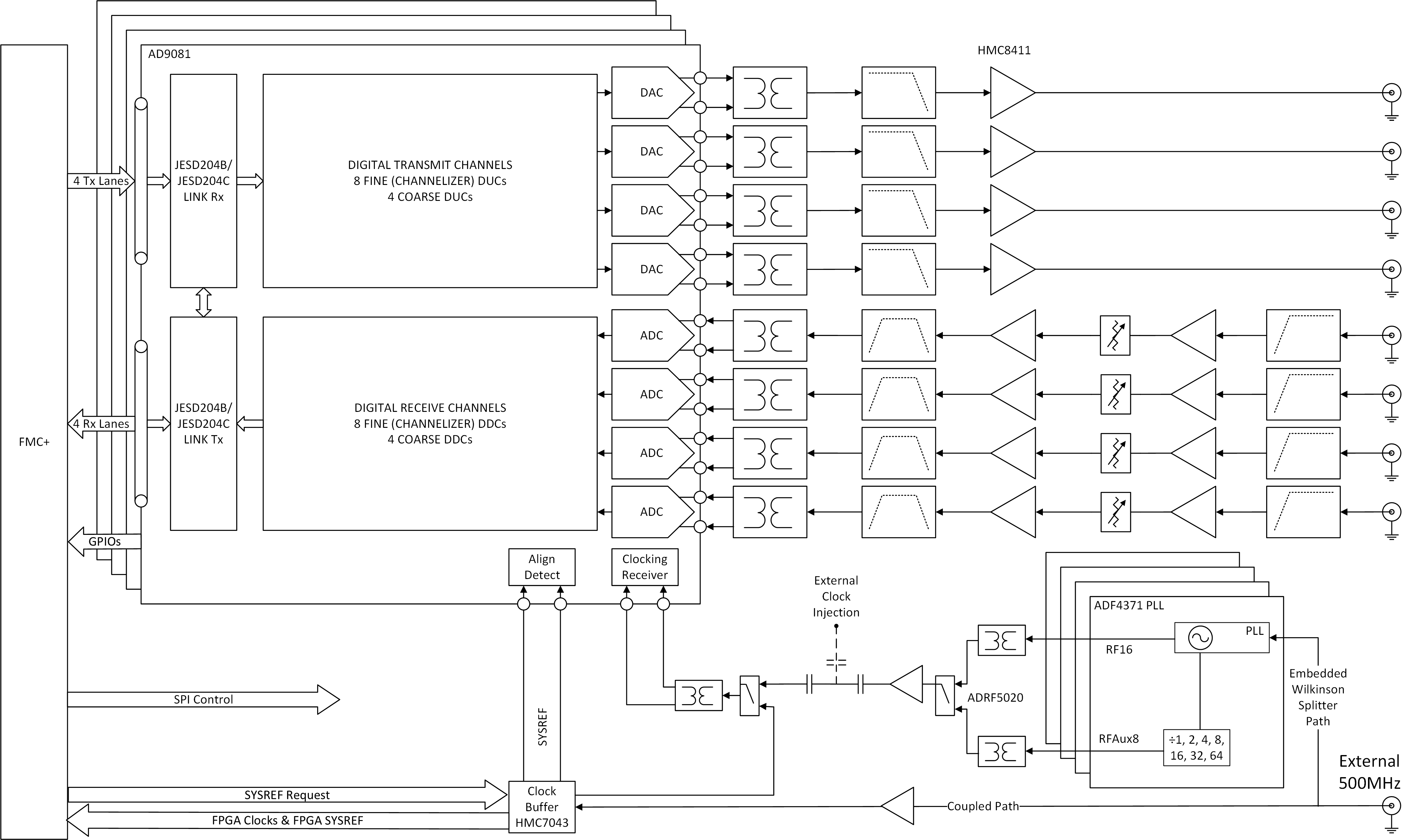
The ADQUADMXFE1EBZ is a multi-channel, wideband system development platform featuring four AD9081 MxFE™ software-defined, direct RF sampling transceivers, along with associated RF front-ends, clocking, and power circuitry. It delivers 16 transmit and 16 receive RF channels (32 digital channels each), exploiting the AD9081’s 12 GSPS DAC and 4 GSPS ADC cores.
The platform highlights a complete system solution. It is intended as a testbed for demonstrating multi-chip synchronization as well as the implementation of system level calibrations, beamforming algorithms, and other signal processing algorithms. The system is designed to mate with a VCU118 Evaluation Board (not included) from AMD Xilinx, which features the Virtex® UltraScale+™ XCVU9P FPGA, with provided reference software, HDL code, and MATLAB system-level interfacing.
The Rx & Tx RF front-end has drop-in configurations that allow for customized frequency ranges, depending on the user’s application, covering L/S/C band (0.1 GHz to ~5 GHz).
In addition to the Quad-MxFE Digitizing Card, the kit also contains a 16Tx/16Rx Calibration Board (ADQUADMXFE-CAL) that is used to develop system-level calibration algorithms, or otherwise more easily demonstrate power-up phase determinism. The Calibration Board also allows the user to demonstrate combined-channel dynamic range, spurious, and phase noise improvements and can be controlled via a free MATLAB add-on when connected to the PMOD interface of the VCU118.
Features:
Multi-channel, wideband system development platform for the AD9081 MxFE™
Mates with VCU118 Evaluation Board (not included)
16x RF Receive (Rx) Channels (32x Digital Rx Channels)
Total 16x 1.5GSPS to 4GSPS ADC
48x Digital Down Converters (DDCs), each including complex NCOs
16x Programmable Finite Impulse Response Filters (pFIRs)
16x RF Transmit (Tx) Channels (32x Digital Tx Channels)
Total 16x 3GSPS to 12GSPS DAC
48x Digital Up Converters (DUCs), each including complex NCOs
Flexible Rx & Tx RF front-ends
Rx: Filtering, amplification, digital step attenuation for gain control
Tx: Filtering, amplification
Multiple system control and analysis tools
IIO Oscilloscope GUI
MATLAB add-ons & example scripts
HDL and embedded software solutions for JESD204B/JESD204C bring-up
JESD204B/C interface support (up to 24.75 Gbps/lane)
On-chip PLL support (Rev. C)
On-board power regulation from single 12V power adapter (included)
Flexible clock distribution
On-board clock distribution from single external 500 MHz reference
Support for external converter clock
Applications:
Phased array radar, electronic warfare (EW), and SATCOM (ADEF)
Communications infrastructure (multiband and mmWave 5G)
Electronic test and measurement
Multi-chip synchronization for power-up phase determinism
System-level amplitude/phase alignment using NCOs
Low-latency ADC-to-DAC loopback bypassing JESD interface
pFIR control for broadband channel-to-channel amplitude/phase alignment
Fast-frequency hopping
High-level block diagram
System integration
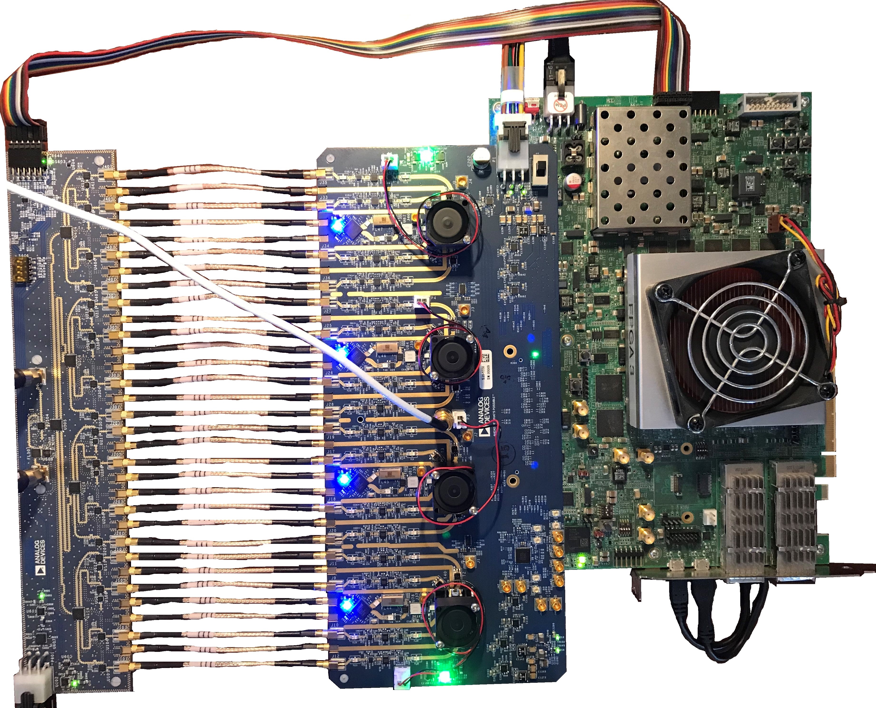
Below is the full integrated system including the VCU118, ADQUADMXFE1EBZ, and ADQUADMXFE-CAL in full operation.
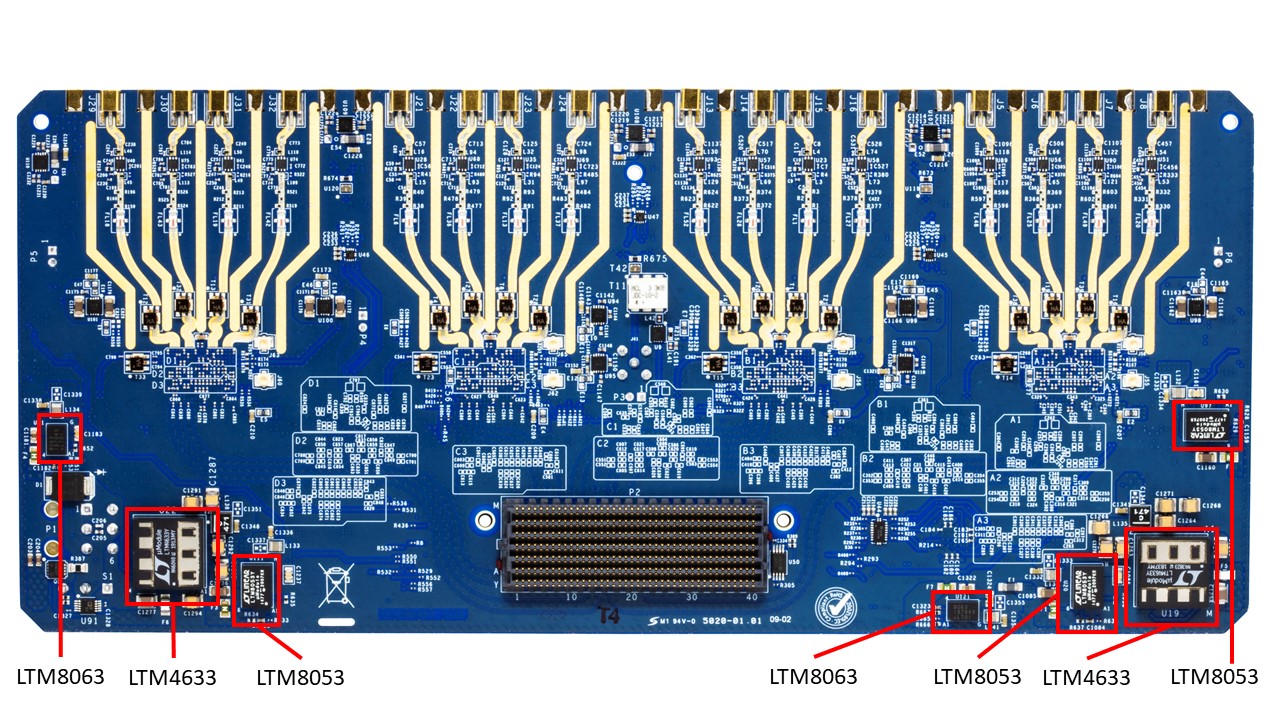
Key component locations
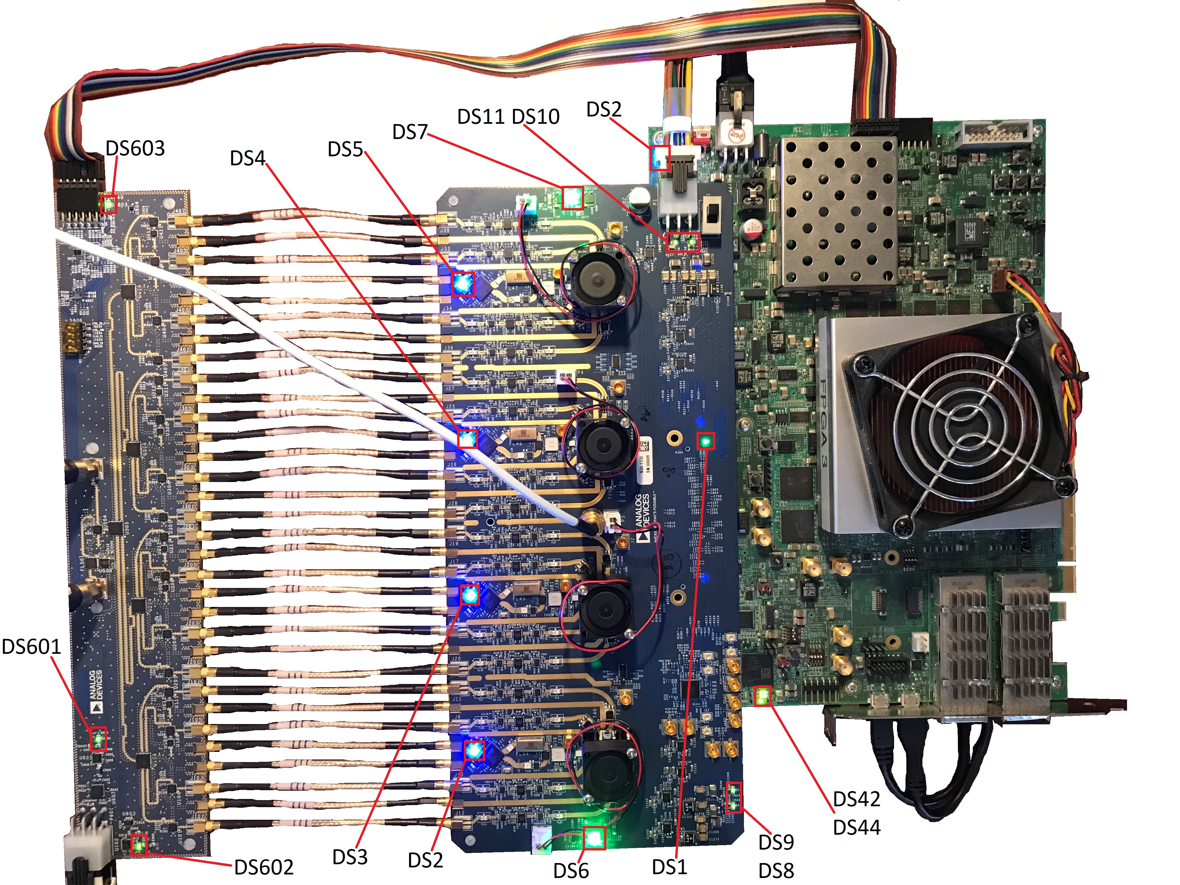
LED status indicators
Recommendations
People who follow the flow that is outlined have a much better experience with things. However, like many things, documentation is never as complete as it should be. If you have any questions, feel free to ask on our Help and Support, but before that, please make sure you read our documentation thoroughly.
Table of contents
Using the evaluation board/full stack reference design that we offer:
Prerequisites — what you need to get started with the setup
Board Hardware Details — Tx/Rx signal paths, clocking architecture, JESD interface, and power distribution
Calibration Board (ADQUADMXFE-CAL) — 16Tx/16Rx splitter/combiner, loopback paths, and power analysis add-on
Multi-Chip Synchronization Guide — MCS theory, One-Shot Sync, NCO Master-Slave Sync, and PLL phase adjustment
-
Using the VCU118/Virtex UltraScale+
Bring-up guide — software setup, power-up sequence, FPGA programming, and MATLAB control
IIO Oscilloscope & Software — software architecture, IIO device mapping, GUI usage, and IIO commands
Design with the AD9081
HDL reference designs:
Resources for designing a custom platform:
Linux drivers:
About the JESD204 utilities:
Videos
Publications
Warning
All the products described on this page include ESD (electrostatic discharge) sensitive devices. Electrostatic charges as high as 4000V readily accumulate on the human body or test equipment and can discharge without detection. Although the boards feature ESD protection circuitry, permanent damage may occur on devices subjected to high-energy electrostatic discharges. Therefore, proper ESD precautions are recommended to avoid performance degradation or loss of functionality. This includes removing static charge on external equipment, cables, or antennas before connecting to the device.
Help and Support
For additional questions or support, please visit the Engineering Zone forum at adef-system-platforms/.