PlutoSDR Quick Start
Most people don’t read instructions, and just want get things going. This is the minimum to get things going, and a few common trouble shooting tips along the way.
1. Install the drivers
Install the drivers for your operating system:
2. Plug the device in to USB, and check things are working
After installing the drivers for your platform, plug in the ADALM-PLUTO via USB and verify that it’s working properly. Follow the platform-specific verification steps from the driver installation pages above.
3. Install Scopy for your host
Download and install Scopy for your host.
4. IIO Oscilloscope vs Scopy 2.0
Scopy 2.0 is the modern replacement for the legacy IIO Oscilloscope application. Both tools provide similar functionality for configuring and testing PlutoSDR, but Scopy 2.0 offers a more polished interface and additional features.
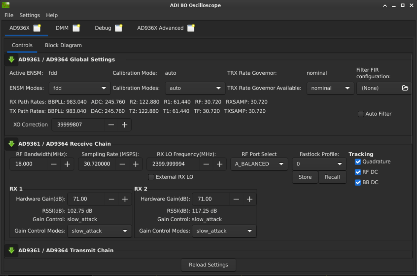
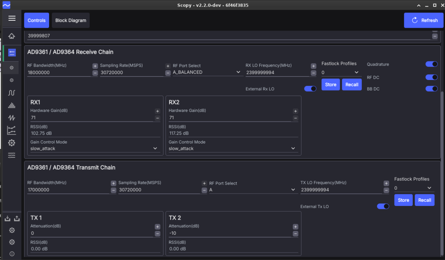
AD936X plugin comparison
Todo
verify this intersphinx target against the live scopy inventory
The AD936X plugin in both tools allows you to configure the transceiver’s receive and transmit chains. Scopy 2.0 provides a cleaner layout with the same controls.
IIO Oscilloscope |
Scopy 2.0 |
|
|
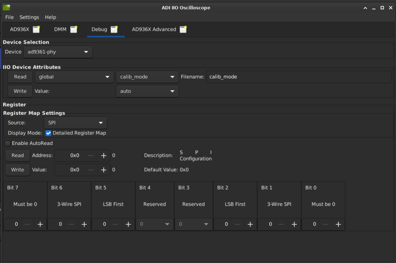
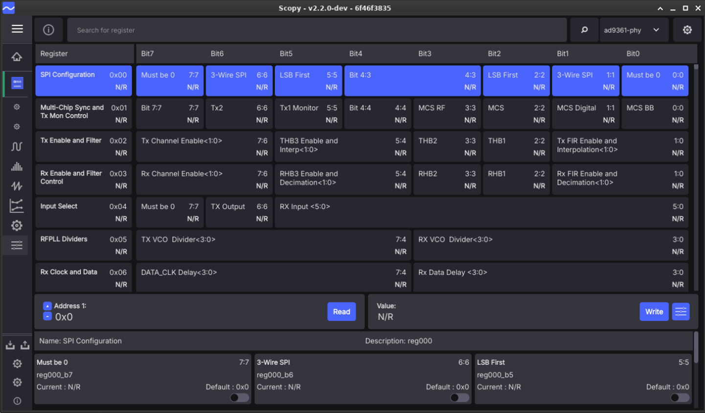
Register map comparison
Both tools provide access to the device register map for advanced debugging. Scopy 2.0 offers a more comprehensive view with register descriptions and bit-level details.
IIO Oscilloscope |
Scopy 2.0 |
|
|
5. Testing PlutoSDR with Scopy 2.0
This section walks you through a basic loopback test to verify your PlutoSDR is working correctly using Scopy 2.0.
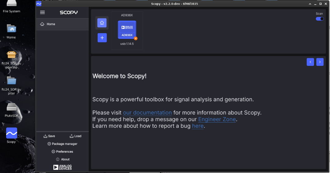
Open Scopy
Launch Scopy on your host. If your PlutoSDR is connected via USB, it should appear automatically as an AD936X device.
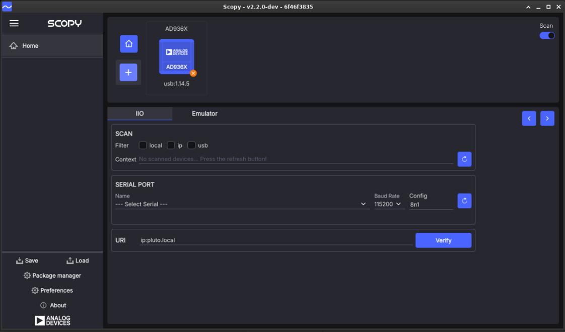
Connect to the device
Click the + button to add a new device. In the IIO tab, enter
ip:pluto.local in the URI field and click Verify to connect.
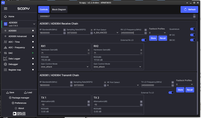
Configure the transceiver
Once connected, open the AD936X plugin. Here you can configure the receive and transmit chain parameters including RF bandwidth, sampling rate, LO frequency, and gain settings.
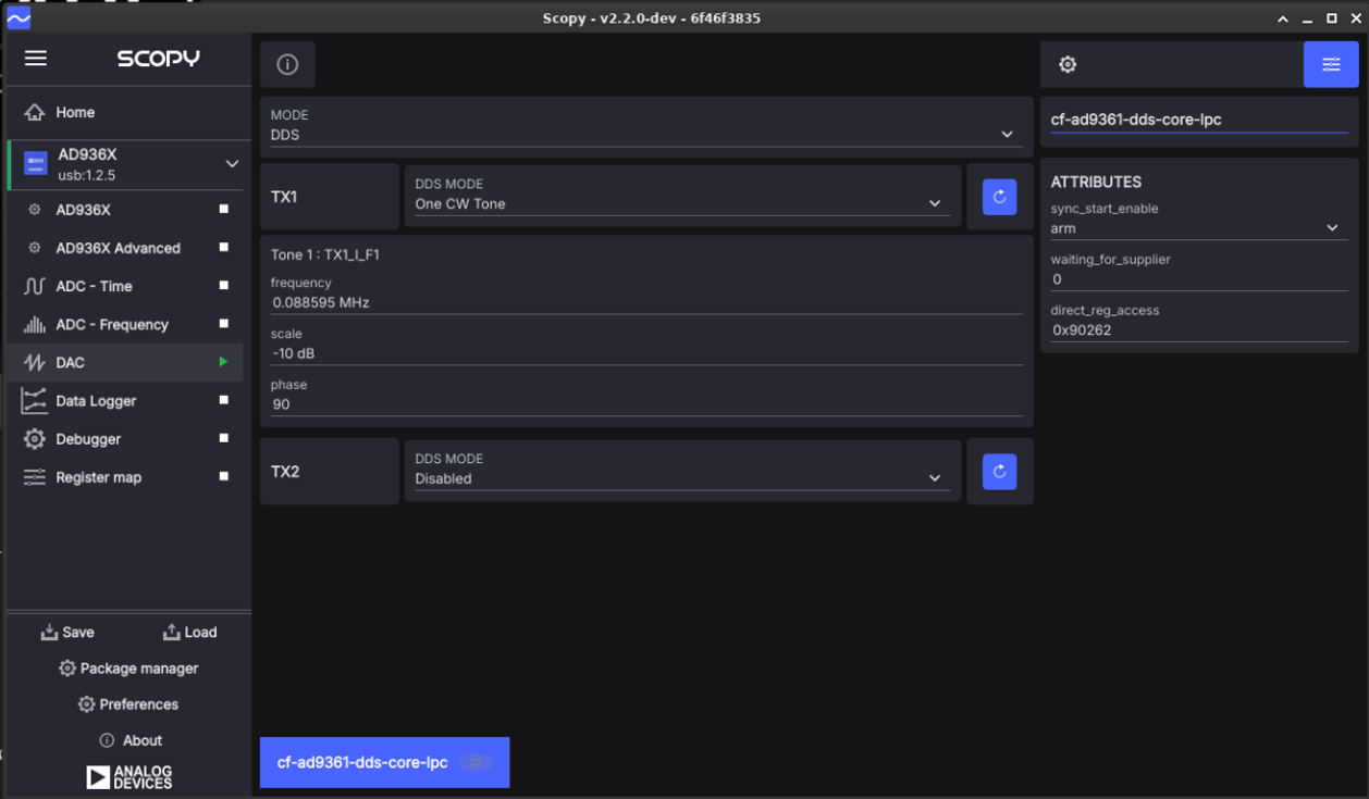
Set up the DAC for signal generation
Navigate to the DAC section. Set the MODE to DDS and configure TX1 to use One CW Tone. Set the desired frequency, scale (amplitude in dB), and phase for your test tone.
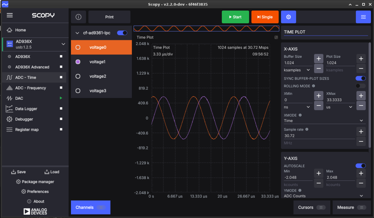
View the signal in the time domain
Open ADC - Time to view the captured signal in the time domain. Click Start to begin acquisition. You should see a sine wave corresponding to your DDS tone.
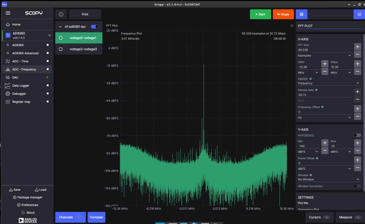
View the signal in the frequency domain
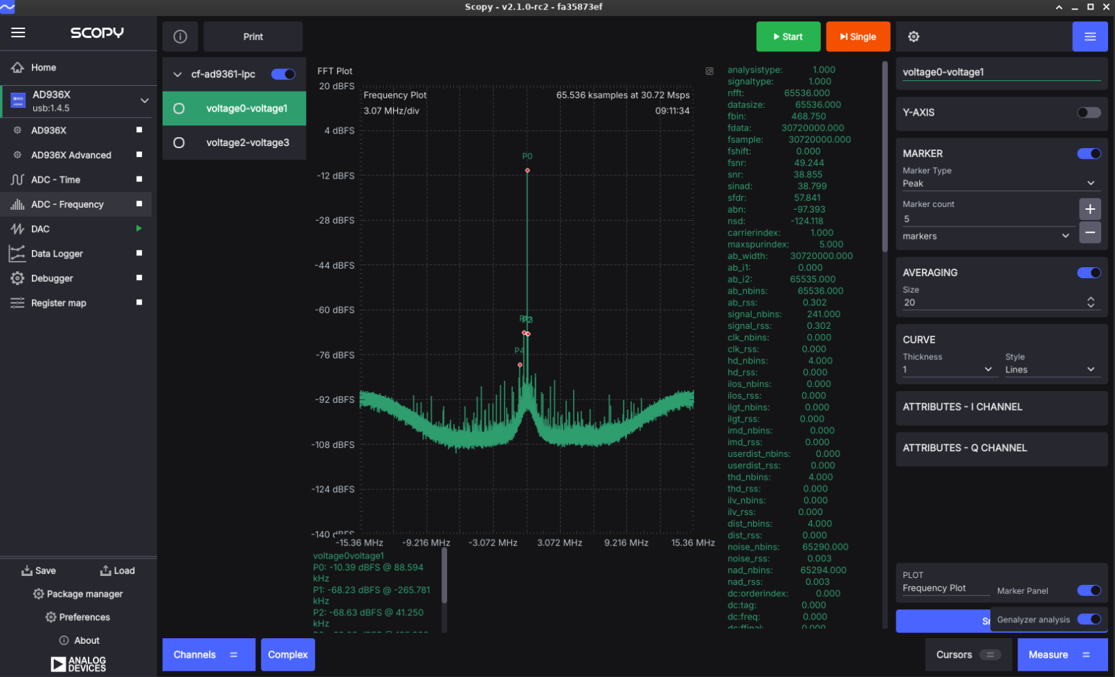
Open ADC - Frequency to view the FFT of the captured signal. You should see a clear peak at your configured DDS frequency.
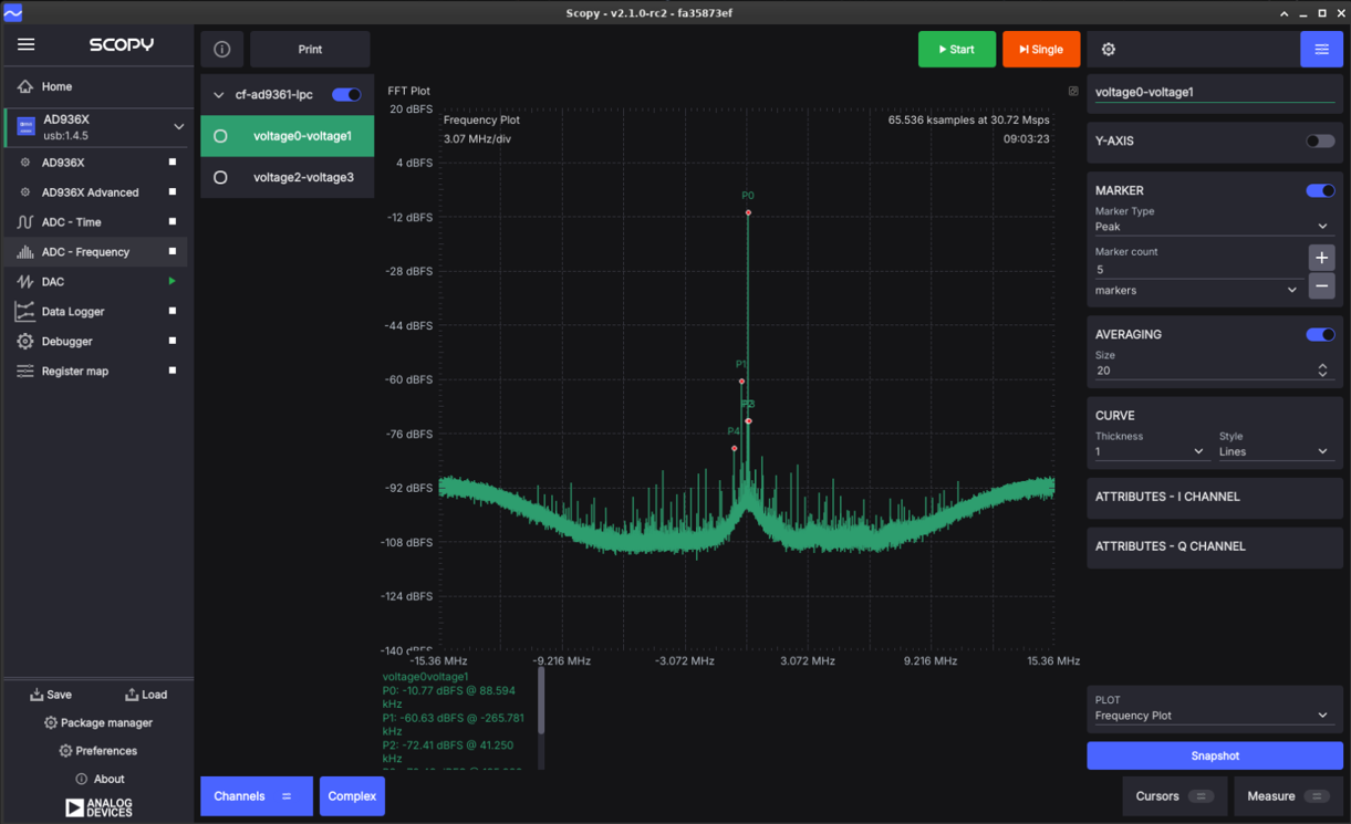
Enable markers for analysis
Enable MARKER in the right panel to identify peak frequencies and their power levels. The markers will display frequency and amplitude information at the bottom of the screen.
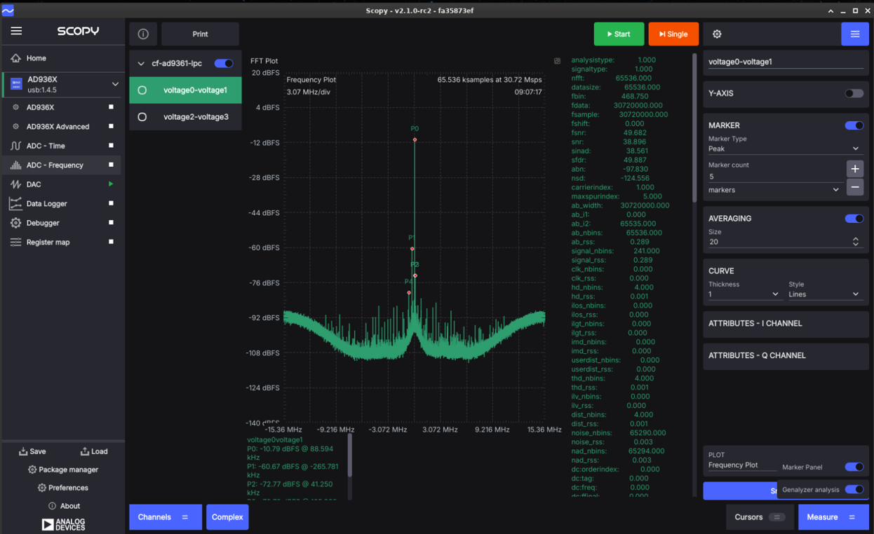
Use Genalyzer for detailed analysis
Enable Genalyzer analysis in the right panel to compute detailed signal quality metrics including SNR, SINAD, SFDR, and other parameters.
Experiment with TX attenuation
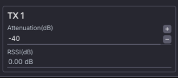
Return to the AD936X plugin and adjust the TX attenuation to see how it affects the received signal level. The images below show the TX attenuation control and the resulting change in signal amplitude.
6. Connect to your favorite SDR framework, and do interesting things
Connect the ADALM-PLUTO to your preferred SDR framework: