Data Acquisition for Input Current Demo
The ADuCM360_demo_cn0336 is a data acquisition demo project for 4-20 mA inputs, for the EVAL-ADICUP360 base board with additional EVAL-CN0336-PMDZ pmod, created using the GNU ARM Eclipse Plug-ins in Eclipse environment.
General description
This project is a good example for how to use EVAL-ADICUP360 board in different combinations with pmod boards. It expand the list of possible applications that can be done with the base board.
The ADuCM360_demo_cn0336 project uses the EVAL-CN0336-PMDZ pmod which is a completely isolated 12-bits, 300 kSPS data acquisition system (with only three active devices) that processes 4 mA to 20 mA input signals.
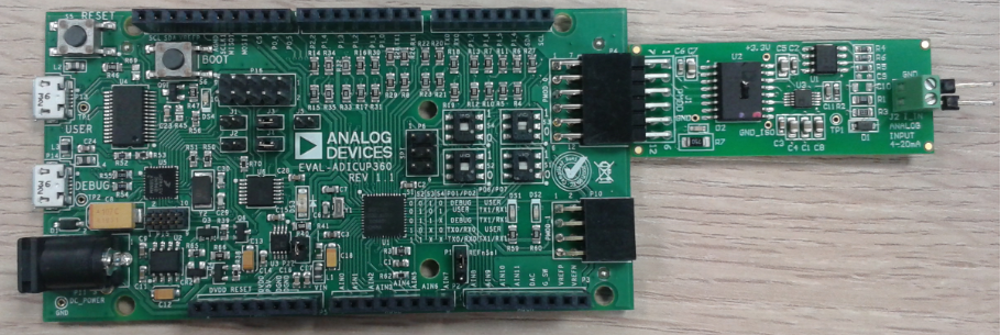
The CN0336 circuit consists of an input current-to-voltage converter, a level shifting circuit, an ADC stage and an output isolation stage. The 4 mA to 20 mA input signal is converted into voltage levels compatible with the input range of the ADC (0 V - 2.5 V). The 12-bits ADC value is received via SPI interface of the EVAL-ADICUP360 board.
The EVAL-CN0336-PMDZ comes with an evaluation software which can help you to test and to calibrate your pmod before you use it.
Note
Please visit CN0336 Software User Guide page to find out how to get and how to use the CN0336 evaluation software.
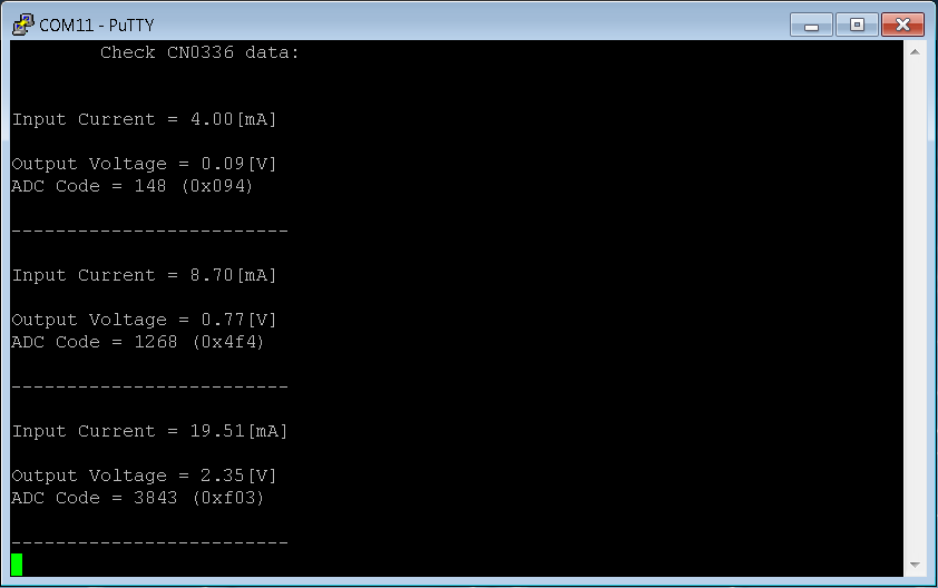
The ADuCM360_demo_cn0336 application processes ADC outputs and provide current and voltage values. You can decide how often the ADC measurements take place (see SCAN_TIME parameter).
A UART interface (115200 baud rate and 8-bits data length) is used to send the results to terminal window: input current value, voltage calculation and ADC code. If the input value is out of range you get an error message which means that you need to check your settings.
To start displaying data acquisition results on a terminal (putty in this case) you need to press ENTER key (CR) from the keyboard and after that the data are updated every time the input values are changed. The output data are send via UART using semihosting.
The project offers two method to calculate the input current, giving you the possibility to get more accurate results (see CN0336 circuit note). You can use transfer function of the circuit which calculate input current based on voltage changed value and circuit gain:
I = Imin + (Vout - Voffset)/Gain
Or you can use the two-point calibration method which used the ADC output values for 2 different measurements: first at Imin = 4 mA (ADC1) and second at Imax = 20 mA (ADC2):
Ix = Imin + [(Imax - Imin)/(ADC2 - ADC1)]*(ADCx - ADC1)
Demo Requirements
The following is a list of items needed in order to replicate this demo.
Hardware
EVAL-ADICUP360
EVAL-CN0336-PMDZ
4mA - 20mA current source
Mirco USB to USB cable
PC or Laptop with a USB port
Software
ADuCM360_demo_cn0336 software
CrossCore Embedded Studio (2.7.0 or higher)
ADuCM36x DFP (1.0.2 or higher)
CMSIS ARM Pack (4.3.0 or higher)
Serial Terminal Program
Such as Putty or Tera Term
Setting up the hardware
To program the base board, set the jumpers/switches as shown in the next figure. The important jumpers/switches are highlighted in red.
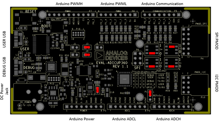
Plug the EVAL-CN0336-PMDZ PMOD in the EVAL-ADICUP360 base board, via the PMOD_SPI port (P4).
Plug in the USB cable from the PC to the EVAL-ADICUP360 base board via the Debug USB.(P14)
Obtaining the Source Code
There are two basic ways to program the ADICUP360 with the software for the CN0336.
Dragging and Dropping the .Bin to the MBED drive
Building, Compiling, and Debugging using CCES
Using the drag and drop method, the software is going to be a version that Analog Devices creates for testing and evaluation purposes. This is the EASIEST way to get started with the reference design.
Importing the project into CrossCore is going to allow you to change parameters and customize the software to fit your needs, but will be a bit more advanced and will require you to download the CrossCore toolchain.
The software for the ADuCM360_demo_cn0336 demo can be found here:
Download
Prebuilt CN0336 Bin File
Complete CN0336 Source Files
Note
For more information on importing, debugging, or other tools related questions, please see the tools user guide.
Configuring the Software Parameters
Converter operation mode - AD7091R_OPERATION_MODE - POWER_DOWN to select power-down AD7091R mode of operation or NORMAL for normal mode (AD7091R.h).
#define AD7091R_OPERATION_MODE POWER_DOWN
Converter scan time - SCAN_TIME - how often (msec) to read conversion results (AD7091R.h).
#define SCAN_TIME 500
Converter reference voltage - VREF - reference voltage (V) for AD7091R converter (AD7091R.h).
#define VREF 2.5
Current calculation formula - CALC_FORMULA - this parameter can be set as TRANSFER_FUNCTION or TWO_POINT_CALIBRATION (CN0336.h).
#define CALC_FORMULA TWO_POINT_CALIBRATION
Data acquisition parameters - all needed parameters for data calculations (CN0336.h).
#define  IMIN           4             /* Imin [mA] */
#define  IMAX           20            /* Imax [mA] */
#define  ADC_MIN        147           /* ADC min for IMIN */
#define  ADC_MAX        3960          /* ADC max for IMAX */
Outputting Data
Serial Terminal Output
In order to view the data, you must flash the program to the EVAL-ADICUP360.
Once complete you will need to switch the USB cable from the DEBUG USB (P14) to the USER USB (P13).
Then follow the UART settings below with the serial terminal program.
Following is the UART configuration.
Select COM Port
Baud rate: 115200
Data: 8 bit
Parity: none
Stop: 1 bit
Flow Control: none
Semihosting must be enables to view the data via the UART
The user must press the <ENTER> key to beginning transmitting the data to the serial terminal.
Data is then updated every time the input values change.
How to use the Tools
The official tool we promote for use with the EVAL-ADICUP360 is CrossCore Embedded Studio. For more information on downloading the tools and a quick start guide on how to use the tool basics, please check out the Tools Overview page.
Importing
For more detailed instructions on importing this application/demo example into the CrossCore Embedded Studios tools, please view our How to import existing projects into your workspace section.
Debugging
For more detailed instructions on importing this application/demo example into the CrossCore Embedded Studios tools, please view our How to configure the debug session section.
Project structure
The ADuCM360_demo_cn0336 project use ADuCM36x C/C++ Project structure.
This project contains: system initialization part - disabling watchdog, setting system clock, enabling clock for peripherals; port configuration for SPI0, UART via P0.6/P0.7; SPI, UART read/write functions; AD7091R control and current-voltage conversion.
In the src and include folders you will find the source and header files related to CN0336 software application. The Communication.c/h files contain SPI and UART specific data, meanwhile the AD7091R.c/h files contain the ADC control data and the CN0336.c/h files contain the data acquisition parts.
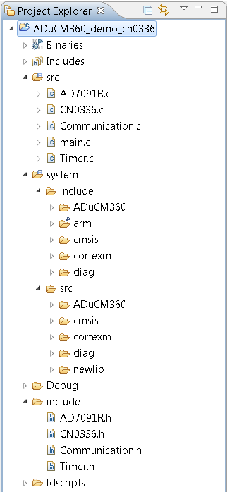
The RTE folder contains device and system related files:
Device Folder – contains low levels drivers for ADuCM360 microcontroller.(try not to edit these files)
system.rteconfig - Allows the user to select the peripherial components they need, along with the startup and ARM cmsis files needed for the project.