Software Guide
Overview
This guide covers the Arduino firmware for the AD-M2KCOMPEDU-EBZ educational add-on board. It walks through building and flashing the firmware, demonstrates signal generation and PWM output, and documents the internal software architecture — including the signal chain, MVC structure, UI state machine, and calibration system.
Arduino Firmware for AD-M2KCOMPEDU-EBZ
The Arduino firmware for AD-M2KCOMPEDU-EBZ is an educational add-on board for the ADALM2000. It has a signal generator (sine, square, triangle, DC) with adjustable amplitude, frequency, DC offset, and a PWM generator with adjustable frequency and duty cycle.
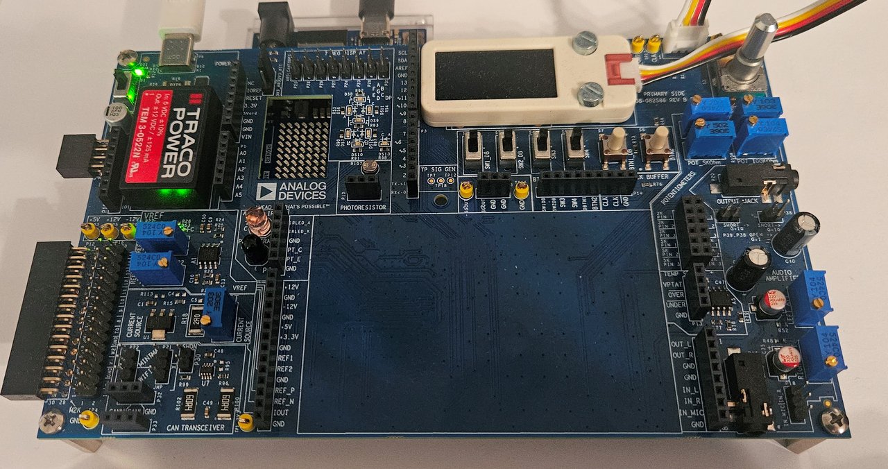
Required Software
Download
Building and Flashing the Board
Arduino IDE
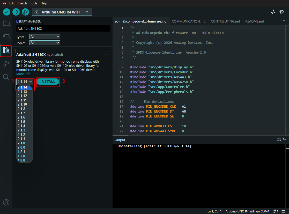
The Arduino IDE does not read the build profile, so libraries must be installed manually via Sketch > Include Library > Manage Libraries. Install the exact versions below for a build that matches the pinned toolchain:
Library |
Version |
Purpose |
|---|---|---|
|
2.1.14 |
OLED display driver |
|
1.12.6 |
Graphics primitives (used by SH110X) |
|
1.17.4 |
I2C/SPI abstraction (dependency of the Adafruit libraries) |
|
0.4.5 |
AD9833 DDS waveform generator driver |
Then:
In the Arduino IDE, open
AD-M2KCOMPEDU-EBZ-firmware.ino.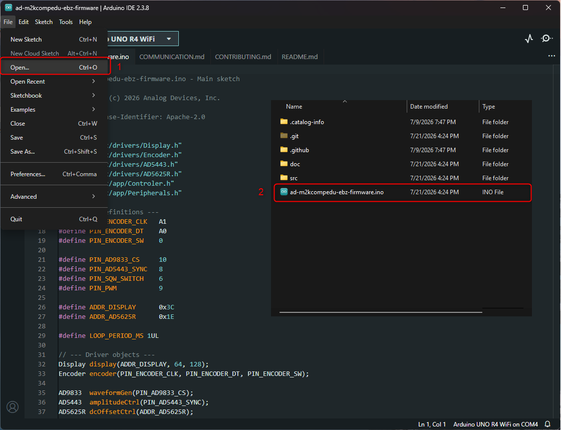
Install the libraries listed above. In the Library Manager:
Select the package.
Choose the exact version from the dropdown.
Click INSTALL.
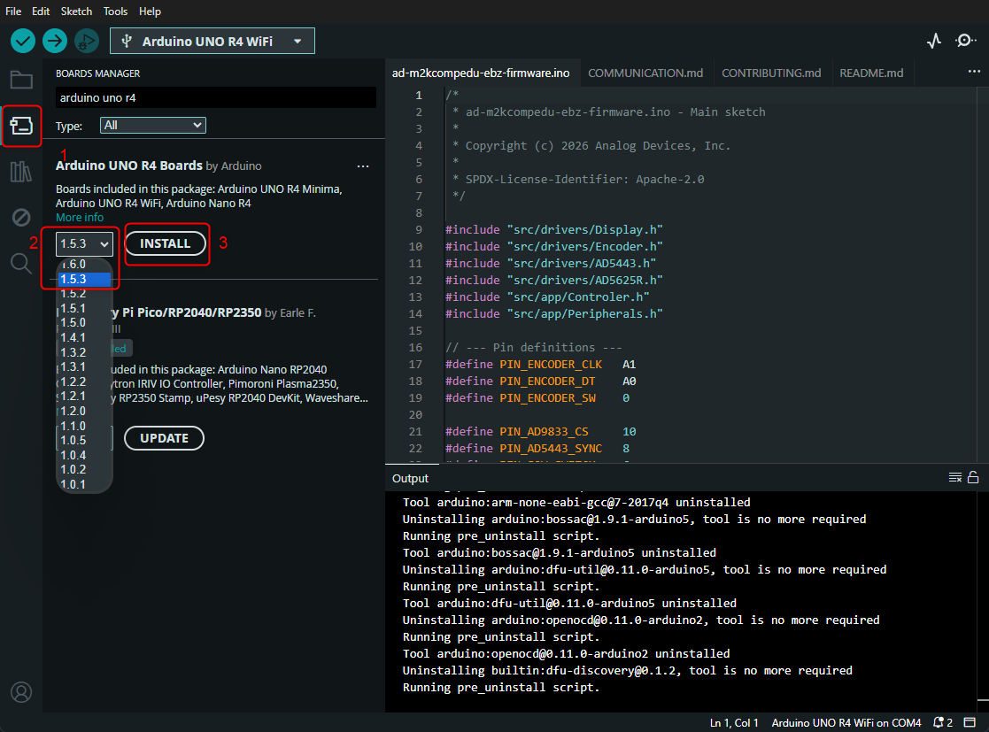
Install the Arduino UNO R4 Boards core, version 1.5.3:
Click Tools > Board.
Select Arduino UNO R4 WiFi > Boards Manager. The version dropdown lets you pick 1.5.3.
Click INSTALL.
Select the correct port via Tools > Port.
Click Upload (or Ctrl + U).
Arduino CLI
The repository includes a sketch.yaml build profile that pins the board
core and all library versions. This is the recommended path — it installs the
exact pinned versions into a sketch-local location and requires no manual
library setup.
From the root of the project directory:
# Compile using the pinned profile (installs the pinned core and libraries)
arduino-cli compile --profile unor4wifi AD-M2KCOMPEDU-EBZ-firmware.ino

# Upload to the connected board
arduino-cli upload --profile unor4wifi --port <port> AD-M2KCOMPEDU-EBZ-firmware.ino
Replace <port> with the serial port (COM3 or /dev/ttyUSB0).
UART is configured at 57600 baud for debug output.
Flashing the Board
Before Flashing
Important
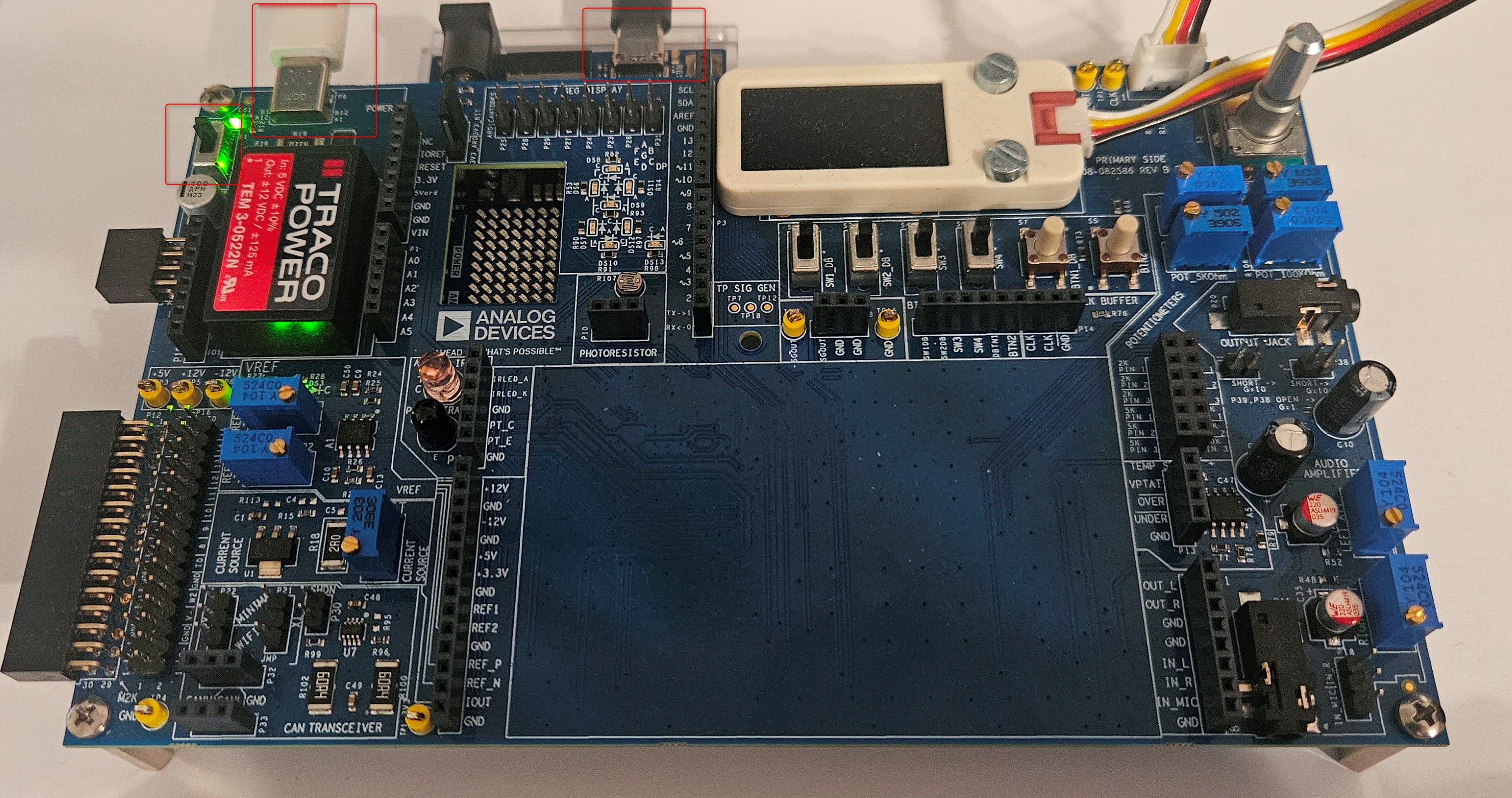
Before uploading the firmware, make sure the board is powered and connected.
Power supply: Connected to the board
USB-C cable: Plugged into the Arduino
Power switch: In the ON position
After Flashing
Once the upload completes, the firmware boots automatically. You should see:
The menu appears on the OLED display.
The Analog Devices animation plays on the UNO R4 LED matrix. The wedge logo is revealed, then the “Analog Devices” text scrolls across.
Example Usage
Important
Make sure that your board has the firmware uploaded, if not see the Building and Flashing the board section.
Generating a Wave
Connect the power supply to the USB-C power port of the board and move the power switch to the ON position.
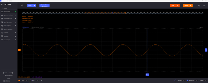
Using the rotary encoder, navigate to Signal Gen -> WaveForm (you can select DC, Sine, Square, or Triangle). Then select the peak-to-peak amplitude, frequency, and offset.
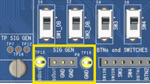
You can view the resulting waveform by connecting a scope to any of the SGOUT test points or header. As a ground reference, you can use any of the test points or headers labeled as GND.
Generating a PWM Signal
Connect the power supply in the USB-C power port of the board and move the power switch to the ON position.
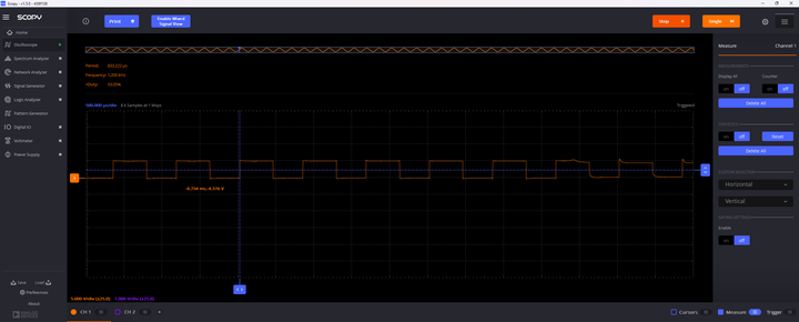
Using the rotary encoder, navigate to PWM Gen -> PWM Out set to ON. Then you can select Frequency and Duty Cycle.

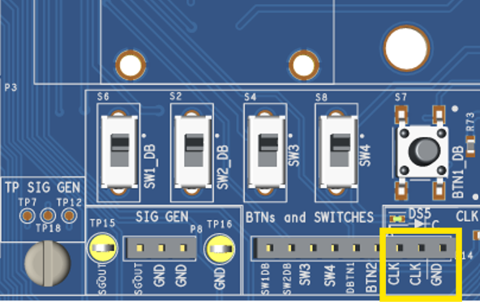
You can view the resulting PWM signal by connecting a scope to any of the CLK-labeled test points or headers. As a ground reference you can use any of the test points or headers labeled as GND.
Further Information
Signal Chain
AD9833 (DDS)  -->  AD5443 (MDAC)  -->  OUT_SG
                       ^
                       |
               AD5625R (DC Offset DAC)
AD9833: Generates the base waveform at the set frequency.
AD5443: MDAC attenuates the AD9833 output by
Data / 4096(does not generate voltage on its own).AD5625R: Generates DC offset via differential pair:
Vout ~ (DAC_A - DAC_B).
Note
For the full analog signal chain schematics and gain derivations, see Signal and PWM/CLK generator in the Hardware Guide.
Amplitude Conversion (V to LSB)
Waveform |
Gain Constant |
Example |
|---|---|---|
Sine / Triangle |
|
1Vpp = 188LSB, 5Vpp = 938LSB |
Square |
|
1Vpp = 34LSB, 5Vpp = 172LSB |
DC Offset Computation
DC_LSB = round(DC_voltage / DcOffperLSB) + LSBOFF
DAC_A  = 2048 + DC_LSB / 2
DAC_B  = 2048 - DC_LSB / 2
Where DcOffperLSB = 0.0031640 V/LSB and LSBOFF is the calibration
correction from EEPROM.
Software Architecture
The firmware is an Arduino sketch following a Model-View-Controller pattern:
AD-M2KCOMPEDU-EBZ-firmware.ino    Entry point (setup + 1ms loop)
src/
  app/
    Controler.cpp/.h              FSM controller, menu tree, state management
    Menu.cpp/.h                   Menu rendering with custom markup formatting
    Peripherals.cpp/.h            Hardware abstraction, refreshFlags-based updates
    CalibrationWizard.cpp/.h      Multi-step interactive calibration
  drivers/
    AD5443.cpp/.h                 SPI driver for amplitude MDAC
    AD5625R.cpp/.h                I2C driver for DC offset quad-DAC
    Display.cpp/.h                SH1107 OLED driver (via Adafruit_SH110X)
    Encoder.cpp/.h                Rotary encoder with debounce and event detection
    LedMatrix.cpp/.h              UNO R4 12x8 LED matrix startup/idle animation
Main Loop
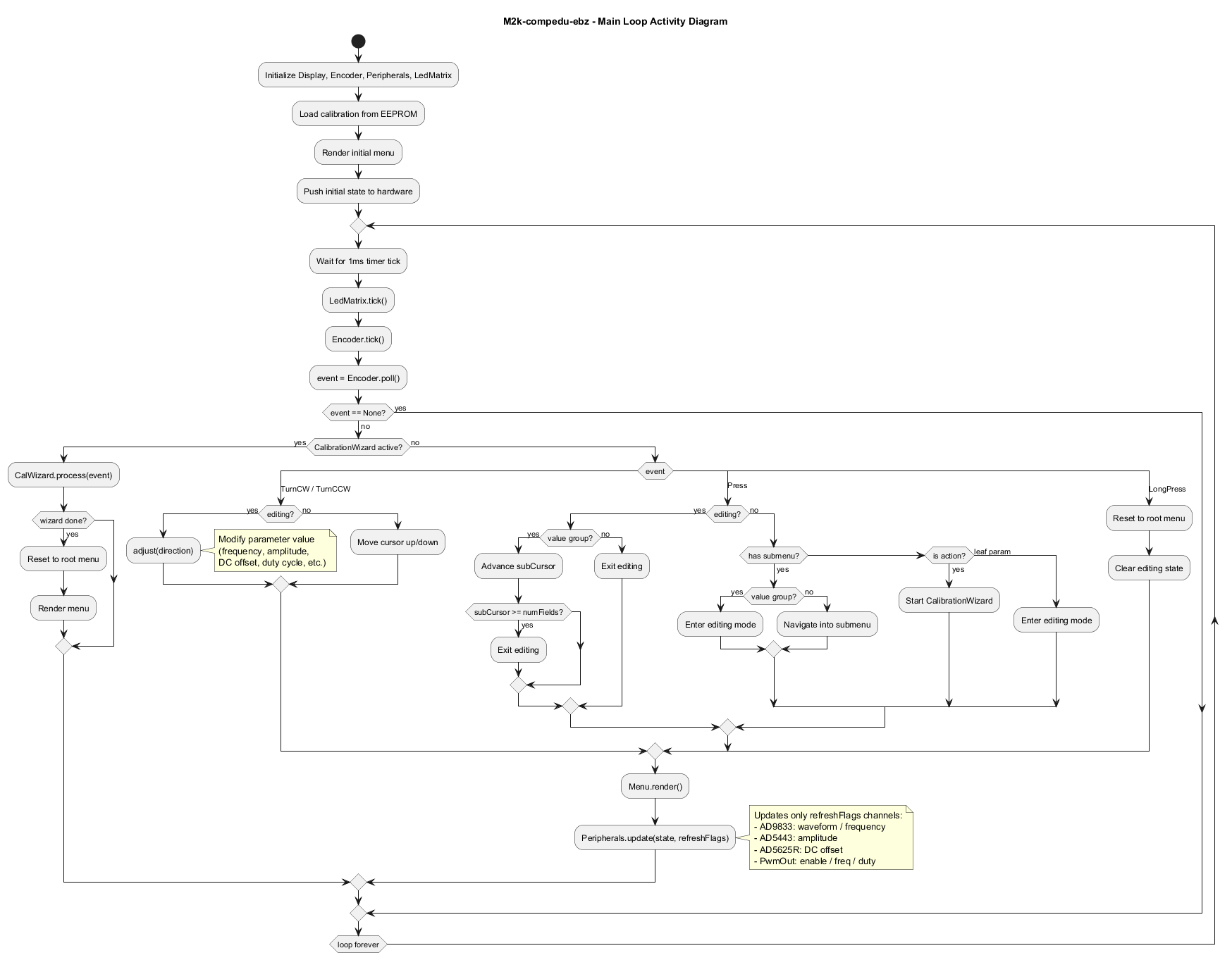
The main loop runs on a 1ms tick. Each iteration:
Polls the rotary encoder for events
Dispatches events to either the CalibrationWizard (if active) or the Controller FSM
Renders the menu to the OLED display
Pushes changed parameters to hardware (only dirty channels via
refreshFlags[])
UI State Machine
Three top-level states:
Navigating: Browse menus (root and submenu). Cursor moves with encoder turns.
Editing: Adjust a parameter value (single param or multi-field value group).
Calibrating: Multi-step wizard for offset and amplitude calibration.
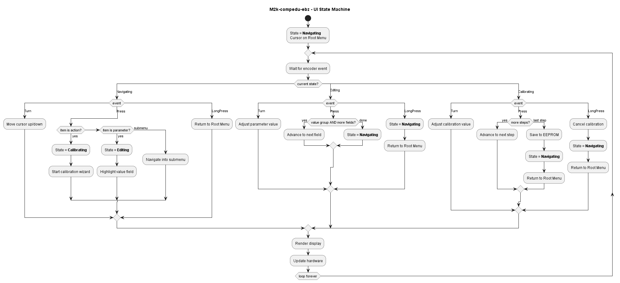
Encoder input mapping:
Rotate: Navigate between menu items (in Navigating) or adjust values (in editing or calibrating).
Short press: Enter a submenu, enter editing mode, or advance calibration step.
Long press: Return to root menu from any state.
Calibration System
Three procedures correct for component tolerances. Each is a step-by-step wizard:
press advances steps, rotate adjusts values. Results are stored in EEPROM at
address 0x10.
Offset Calibration
Corrects the DC offset zero-point by adjusting LSBOFF.
Press to start. Firmware forces DC mode with DC = 0.0V. OLED displays: “Connect Voltmeter to Sig Out, Rotate until Vout ~ 0, then Press”.
Rotate to adjust
LSBOFFuntil the voltmeter reads 0V.Press to store. New
LSBOFFvalue saved to EEPROM.
Sine Amplitude Calibration
Corrects sine amplitude gain at two reference points:
Press to start. Firmware sets Sine, 1KHz, 1Vpp, DC = 0V.
Rotate to adjust
LsbCal_SineAmp1Vuntil scope reads exactly 1Vpp.Press to advance. Amplitude changes to target 10Vpp.
Rotate to adjust
LsbCal_SineAmp10Vuntil scope reads exactly 10Vpp.Press to store.
Square Wave Amplitude Calibration
Same procedure as sine calibration, but uses SqwGain_VperLsb and adjusts LsbCal_SqWAmp1V
/ LsbCal_SqWAmp10V.