ADRV9009-ZU11EG
This guide provides instructions on how to set up and test the AD-FMCXMWBR1-EBZ on the ADRV9009-ZU11EG RF-SOM with the ADRV2CRR-FMC carrier.
Overview
The production testing of AD-FMCXMWBR1-EBZ (DUT) is automated. The test procedure runs on ADRV9009-ZU11EG RF-SOM.
Creating an SD test card
Write the latest available SD card image to a spare card and prepare the card to boot into Linux.
Tip
To write an image on an SD card you can follow the instructions here.
Required hardware
ADRV2CRR-FMC carrier board
ADRV9009-ZU11EG RF-SOM with heat plate and heat sink fitted
TE150A1251F01 power supply (or similar)
SD card with testing procedure
Power rails cable (custom, available in the AD-FMCXMWBR1-EBZ kit)
FFSD-20-D-12.00-01-N ribbon cable (available in the AD-FMCXMWBR1-EBZ kit)
AD-FMCBRIDGE1A TEST BOARD
QR code scanner: QUICKSCAN QD2430 Datalogic
USB 3.0 4-Port Hub: Targus ACH154
Keyboard
Ethernet cable for network connection
USB Adapter: USB Type C Plug, USB Type A Receptacle
Display port monitor and cable
Required setup
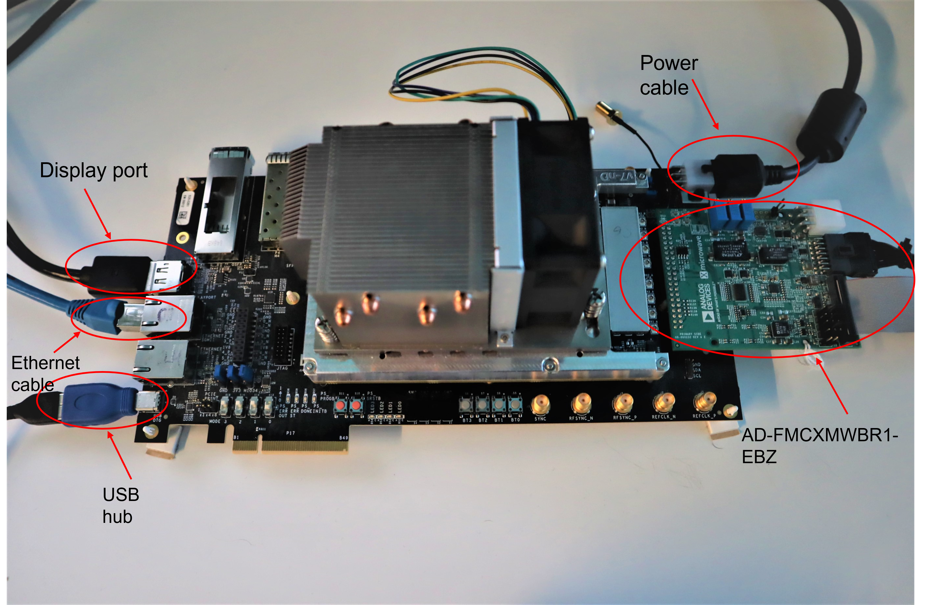
First, the ADRV9009-ZU11EG setup should be built. Please refer to the ADRV9009-ZU11EG Quick Start Guide.
ADRV2CRR-FMC should be powered with the TE150A1251F01 power supply and connected to a network with the ethernet cable.
The screen is connected to ADRV2CRR-FMC through a display port cable. If there is no image shown on the screen at the first boot, please refer to the guide.
Connect the USB OTG adapter and plug the USB Port Hub. In the Port Hub will be connected the keyboard and the QR code scanner.
Plug the AD-FMCXMWBR1-EBZ into the FMC connector of the ADRV2CRR-FMC.
Important
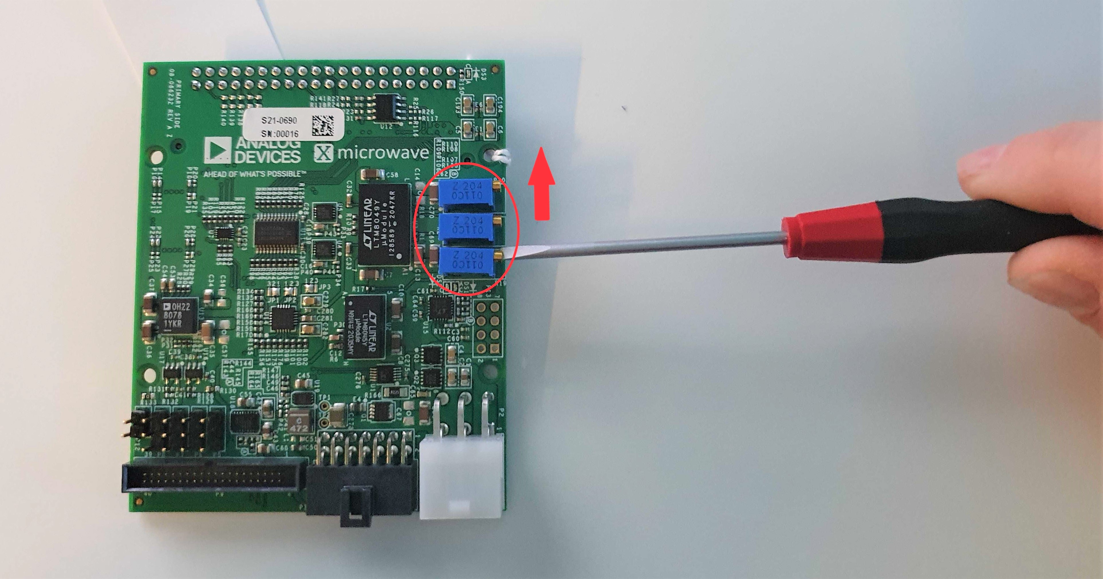
Make sure that the potentiometers R19, R2, R20 are adjusted to maximum. (After the last turn a click sound can be heard.)
Important
Before testing, please make sure that P5, P6, P8, P39, P40, P50, P51 have jumpers connecting pin 1 and pin 2.
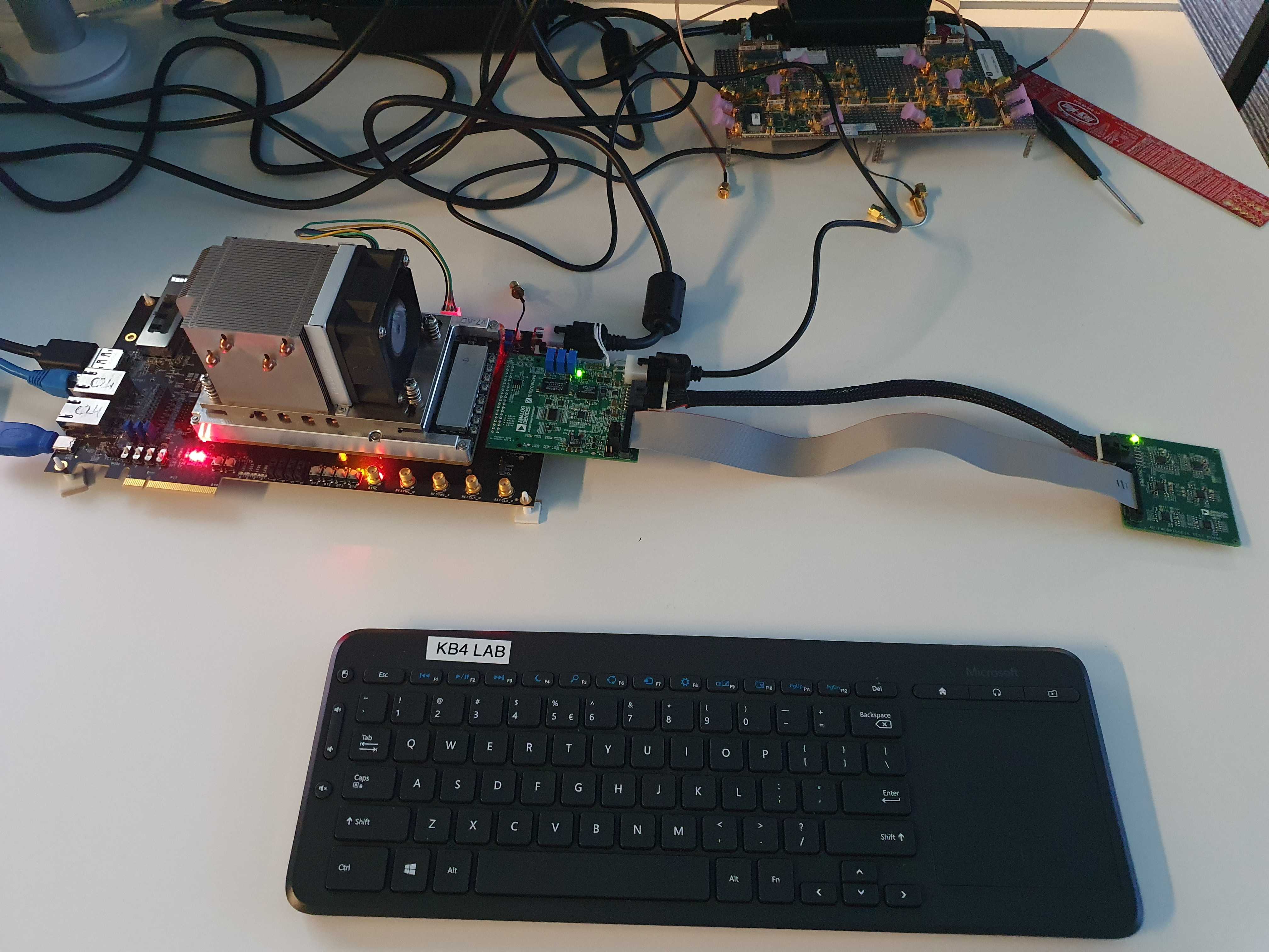
Use the cables to connect the AD-FMCXMWBR1-EBZ to the TEST BOARD.
Test process
Important
Make sure that the full setup is connected when powering up or rebooting the system.
After the connections are done as explained in the “Required setup” section, power up by switching S12 of ADRV2CRR-FMC to on position. When booting, it is mandatory to have the full setup, with the AD-FMCXMWBR1-EBZ board connected. This way, the devices on the test board will be probed correctly at startup. The test instructions will prompt on the screen and the testing should be done using the following steps:
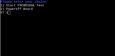
Select the appropriate command from the list. To start the test press 1 on the keyboard then press enter.
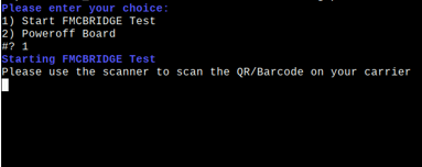
Test procedure will start, then you will be asked to scan the QR/Barcode on the board.
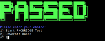
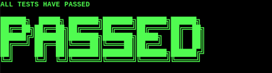
The program will start, the tests are performed automatically and will show the message PASSED/FAILED at the end of the procedure.

To test another board, select option (2) to power off the setup, before using the physical switch and disconnecting AD-FMCXMWBR1-EBZ.