EVAL-CN0216-ARDZ Shield
CN-0216 is a precision weigh scale signal conditioning system. It uses the AD7791, a low power buffered 24-bit sigma-delta ADC along with dual external ADA4528-2 zero-drift amplifiers. This solution allows for high dc gain with a single supply.
Ultralow noise, low offset voltage, and low drift amplifiers are used at the front end for amplification of the low-level signal from the load cell. The circuit yields 15.3 bit noise-free code resolution for a load cell with a full-scale output of 10 mV.
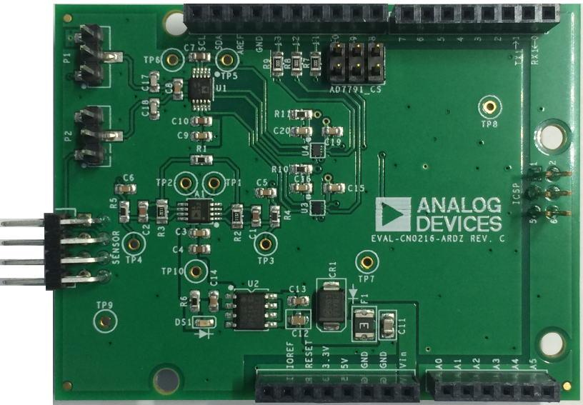
This circuit allows great flexibility in designing a custom low-level signal conditioning front end that gives the user the ability to easily optimize the overall transfer function of the combined sensor-amplifier-converter circuit. The AD7791 maintains good performance over the complete output data range, from 9.5 Hz to 120 Hz, which allows it to be used in weigh scale applications that operate at various low speeds.
Important
Extremely important to note that the EVAL-CN0216-ARDZ is powered from the VIN connector on the Arduino Uno header. This is because the bridge drive voltage of the EVAL-CN0216-ARDZ requires more than 5V to power the bridge. Therefore it is required to supply power from the baseboard through the DC power connector in order for proper functionality. The board will not work properly if you try only to power it from the USB.
Connectors and Jumper Configurations
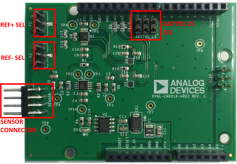
Sensor Connector
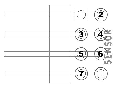
Pin Number |
Pin Function |
|---|---|
Pin 1 |
Not Used |
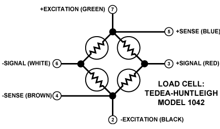
Pin 2 |
|
Pin 3 |
|
Pin 4 |
|
Pin 5 |
|
Pin 6 |
|
Pin 7 |
|
Pin 8 |
Not Used |
REF SEL / Bridge Configuration
These set of jumpers allow the circuit to be configured for use with 4-wire or 6-wire load cells.
Note
Any 4 or 6 wire load cells can be used with the EVAL-CN0216-ARDZ. The Tedeah Huntleigh Model 1042 load cell was used during testing.
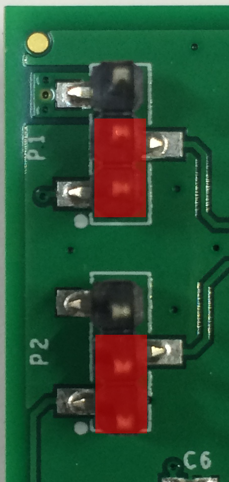 Place jumpers/shunts as shown above for 6-wire resistive bridge configuration
P1 - Connects ADC REFIN+ to Sensor +Sense pin
P2 - Connects ADC REFIN- to Sensor -Sense pin
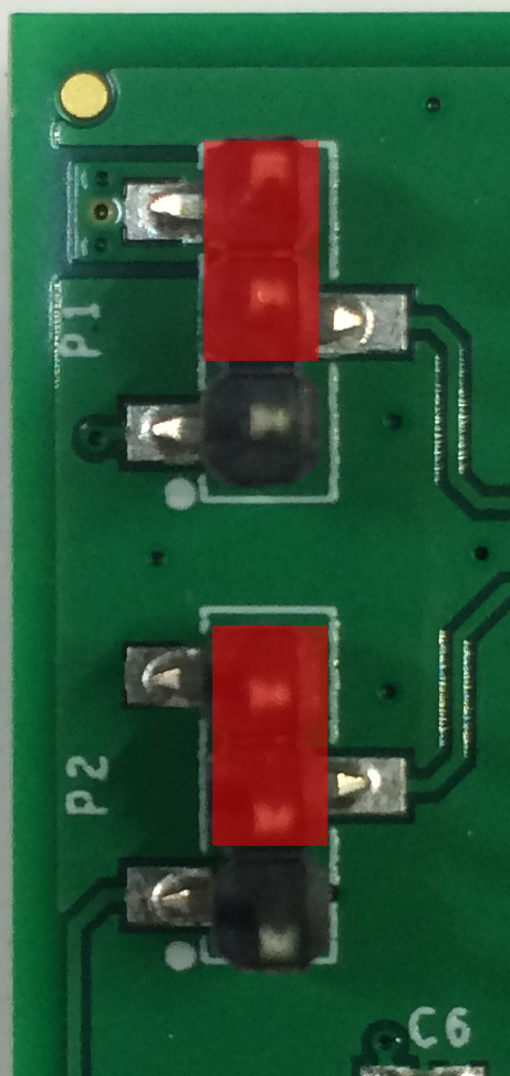 Place jumpers/shunts as shown above for 4-wire resistive bridge configuration
P1 - Connects ADC REFIN+ to 5V supply
P2 - Connects ADC REFIN- to GND
Chip Select
This set of jumpers allows for changing the pin mapping of the AD7791 chip select line to different Arduino digital pins. Place jumper/shunt as shown to connect to the corresponding Digital IO pin
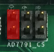 CS - Arduino Digital Pin 10
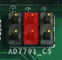 CS - Arduino Digital Pin 9
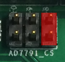 CS - Arduino Digital Pin 8
Note
If using an EVAL-CN0216-ARDZ board prior to Rev.C: To change the CS pin, Install a 0-ohm resistor to resistor pads R7,R8 or R9
R7 - Arduino Digital Pin 8
R8 - Arduino Digital Pin 9
R9 - Arduino Digital Pin 10
Schematic, Bill of Materials, Gerber Files, Layout Files
Download
EVAL-CN0216-ARDZ Rev C Files
EVAL-CN0216-ARDZ Rev B Files
Change Log
RevB to RevC:
U3 (from ADG3304BRUZ to NLSX4402FMUTCG)
U4 added (NLSX4402FMUTCG)
C19 and C20 added (0.1uF)
R7, R8, R9 added to short MOSI, MISO, SCLK lines between ICSP and arduino D11, D12, D13
AD7791_CS header added