AD-96TOF1-EBZ Calibration Guide
Introduction
The AD-96TOF1-EBZ is a pulsed Time-of-Flight (ToF) system. Is consists of a CCD sensor, an illumination source (VCSEL), and an analog front-end (AFE) with a ToF processor. To calculate depth a target scene is illuminated, the returned light is captured by the CCD sensor. The AFE reads the captured data and processes it to depth. In the current setup, there are 3 modes that can be programmed into the AFE to operate the camera at different ranges. Each mode operates on different firmware located in the config/BM_Kit_RevC/ or config/BM_Kit_RevD/ directory of the calibration folder. Depending on the board version, the folder from config/BM_Kit_RevC or BM_Kit_RevD must be renamed to config/BM_Kit before running the calibration software.
Calibration Overview
Calibration is required for the AD-96TOF1-EBZ to map the depth output of the system to the real world. The accuracy of depth is dependent on the calibration environment as well as the target environment conditions. Depth calibration is performed by placing a target at the known distance in from of the TOF system. The system runs the specific mode that is being calibrated. During calibration the illumination pulse of the system is delayed relative to the capture time to simulate different distances, this is referred to as a sweep. The captured data is used to generate a gain, offset, and look-up table. Each mode requires its own calibration and parameters.
Calibration Pipeline
The following procedure takes place when running a calibration (“params” are configurable in JSON files specified later in this document):
Firmware specified from the .json file is loaded into the system;
The system is turned on and allowed to run for a certain warmup period;
The sweep starts and a specified number of depth frames are collected for each sweep step;
Calibration parameters are calculated and stored into new firmware files;
Firmware files are stored to /”results_path”/”unique_id”/”mode”/latest/lf_files;
The user can run these files directly from Example.py or can load these files into EEPROM and then run from Example.py.
Physical Setup
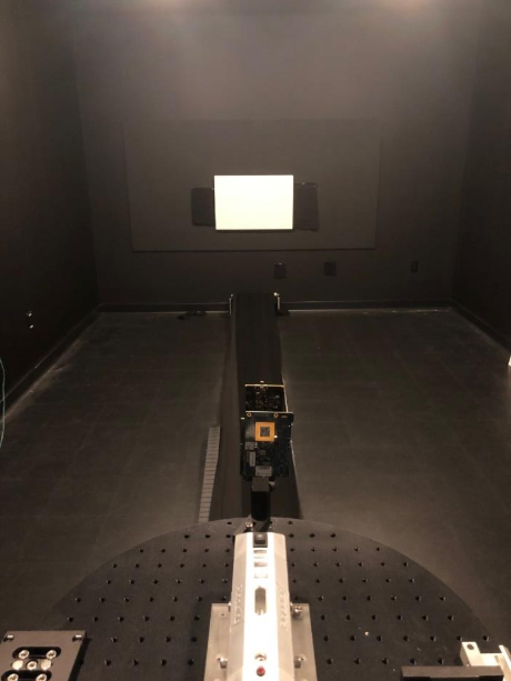
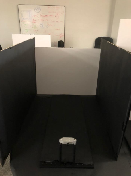
To run a linear calibration a target is placed a known distance away from the ToF system. The reflectivity of the target is dependent on the final use case of the system. For the AD-96TOF1-EBZ calibration, a target of 98% reflectivity for 940nm wavelength light is used. It is also important to keep the target parallel to the sensor. Please use Calibration_Assembly_Doc.pdf as a reference to any calibration setup. Setting up the correct environment is essential for a valid calibration. One major factor that leads to incorrect calibration is multipath. This occurs when light bounces off multiple surfaces and returns to the sensor. This corrupts the data read from the sensor and therefore shifts the final depth value. While completely removing this effect is difficult, steps can be taken to reduce its error contribution. The preferred method to reduce the effect of multipath is to calibrate the sensor in an open room. The sides of the path in between the system and the target should be empty with the closest object being meters away. The floor or bench which the system and target sit on should be covered in low reflectivity material. As shown in the Calibration_Assembly_Doc.pdf, another method is to cover any surfaces on the sides of the path between the system and the target with low reflectivity material. This method is used when there is no access to open space. If the sides and bench spaces are not covered and are highly reflective, the calibration will likely be inaccurate. While the methods above can be used as general guidelines, the best results are determined by the use case. It is recommended to run calibration in the target environment to achieve better accuracy.
Calibration Configuration
To run a calibration first it is necessary to enter the correct parameters to a config file provided with each set of firmware files. The config file is in JSON format. Each mode comes with a recommended calibration config file sweep_config_mode.json in the firmware directory. The following parameters are typically adjusted:
verify_sweep: Allows you to check if the calibration was done correctly by redoing the sweep with the calibration parameters;
unique_id: Allows the user to specify between cameras or experiments;
frame_count: Changes the number of frames collected per sweep step;
warmup_time: Specify how long the camera warms up before calibration;
target_distance: Specify the distance of the target from the sensor in mm.
The parameters available in the config file are shown below. (Supported parameters are highlighted, the unhighlighted parameters are not to be modified)
Parameter |
Value |
Description |
|---|---|---|
mode |
string – (“near”, “mid”, “far”) |
Specifies which mode is calibrated |
calibrate |
bool |
Run calibration |
verify_sweep |
bool |
Run calibration verification |
calib_type |
string – (“Sweep”) |
Calibration Type |
verification_type |
string – (“Sweep”) |
Verification Type |
calculate_metrics |
bool |
Generate metrics (Only works with verify sweep) |
firmware_path |
string – (Path to firmware from |
calibrate_single_mode.py) | Firmware path |
unique_id |
string – (Numerical Values only) |
Specify Unique ID |
repeat_num_filename |
string |
|
hpt_data_filename |
string |
|
data_filename |
string |
|
non_linear_off_lf_file |
string |
|
non_linear_off_calib_lf_file |
string |
|
seq_info_filename |
string |
|
pulse_count_min |
int |
|
pulse_count_max |
int |
|
raw_frame_height |
int |
|
raw_frame_width |
int |
|
window_x |
int |
|
window_y |
int |
|
frame_height |
int |
|
frame_width |
int |
|
frame_count |
int |
Specify how many frames are |
captured per simulated distance |
warmup_time |
int |
Specify the warmup time before calibration |
EEPROM configuration
To store a calibrated files to EEPROM the eeprom_replace_config.json in the calibration folder must be modified. The JSON parameters are shown below:
Parameter |
Value |
Description |
|---|---|---|
mode |
string – (“near”, “mid”, “far”) |
Specifies which mode is being stored to eeprom |
firmware_path |
string |
Specifies path to firmware with calibrated parameters |
cal_map_path |
string |
Specifies path to store calibration data which is currently on EEPROM |
Calibrate and store to EEPROM Example
The following steps run through a near mode calibration with the target positioned at 300mm:
Place target 300mm away from the sensor;
Modify the following parameters in the sweep_config_near.json file, located in the firmware path (aditof_sdk/tools/calibration-96tof1/config/BM_Kit/Near):
“unique_id”: “0001”
“target_distance”: 300
“results_path”: “saved_results”
Open terminal and run the following commands:
cd aditof_sdk/tools/calibration-96tof1
sudo python3 calibrate_single_mode.py config/BM_Kit/Near/sweep_config_near.json
The calibrated firmware and data will be stored in saved_results/0001/near
In config/eeprom_replace_config.json modify the following parameters:
“mode”: “near”
“firmware_path”: “saved_results/0001/near/latest/lf_files”
From the previously opened terminal run the following command:
sudo python3 eeprom_replace_cal.py config/eeprom_replace_config.json
Calibrated firmware is now stored in EEPROM.
Note
To be added.
Download