User guide
Hardware guide
Analog Inputs
HMCAD1520-EBZ / HMCAD1511-EBZ evaluation board has four input channels that supports single-ended to differential conversion with the use of a balun. By default, all input channels 1-4 (SMAs J3, J5, J6 and J7) are balun-coupled. Alternatively, input channel 1 (SMAs J3 and J4) can be configured to differential to differential conversion, and input channel 2 (SMA J5) can be configured to single-ended to differential conversion using the onboard LTC6419 high-speed differential ADC driver.
Refer to the table below for the optional amplifier configuration.
Analog input channel number |
Default Input Driver, AC/DC coupling |
Signal type on Input/Output |
Install |
Uninstall |
|---|---|---|---|---|
1 |
LTC6419, DC coupling, Unity Gain |
Differential/Differential |
R41, R42, R44, R45, R60, R61 |
C51, C52, R23, R24, R56, R57 |
2 |
LTC6419, DC coupling, Unity Gain |
Single-Ended/Differential |
R46, R58, R59 |
C53, R54, R55, R23, R24 |
Analog Input Vcm
the HMCAD1511 / HMCAD1520 supplies the common mode voltage at half-supply (0.9V) for all analog input channels. No external supply is needed for the input Vcm.
Power supply
The power supply comes from the FMC connector, given by the FPGA.
Warning
The recommended VADJ value for each FPGA carrier can be found in the corresponding README.md file here.
Both the HMCAD1520 and HMCAD1511 are being supplied by ADM7154 with 1.8V. The board can be modified to bypass the LDO so the HMCAD1520 and HMCAD1511 are directly supplied by the LTM8078 DC-DC regulator. To do this, change components C3 to 100uF, R6 to 200k, and install a ferrite bead to R9. Also, uninstall R8 and R10.
The supply rails for other components on the board (crystal, amplifier, etc) are isolated to the HMCAD1520 and HMCAD1511 supply rail. Refer to the board schematics for more info.
Clock
The HMCAD1520-EBZ evaluation board uses an external 1GHz clock source on SMA J1 as default.
The HMCAD1511-EBZ evaluation board has an on-board 1GHz crystal for clocking the HMCAD1511. The user can also configure the board to use an external clock source.
Refer to the table below for alternative clock configuration.
Clock Configuration |
Install |
Uninstall |
|---|---|---|
Onboard |
R13 |
R12 |
External |
R12 |
R13 |
Schematic, PCB Layout, Bill of Materials and other Files
Software guide
The evaluation board is supported with the Libiio library. This library is cross-platform (Windows, Linux, Mac) with language bindings for C, C#, Python, MATLAB, and others. One easy to example that can be used with it is:
Results
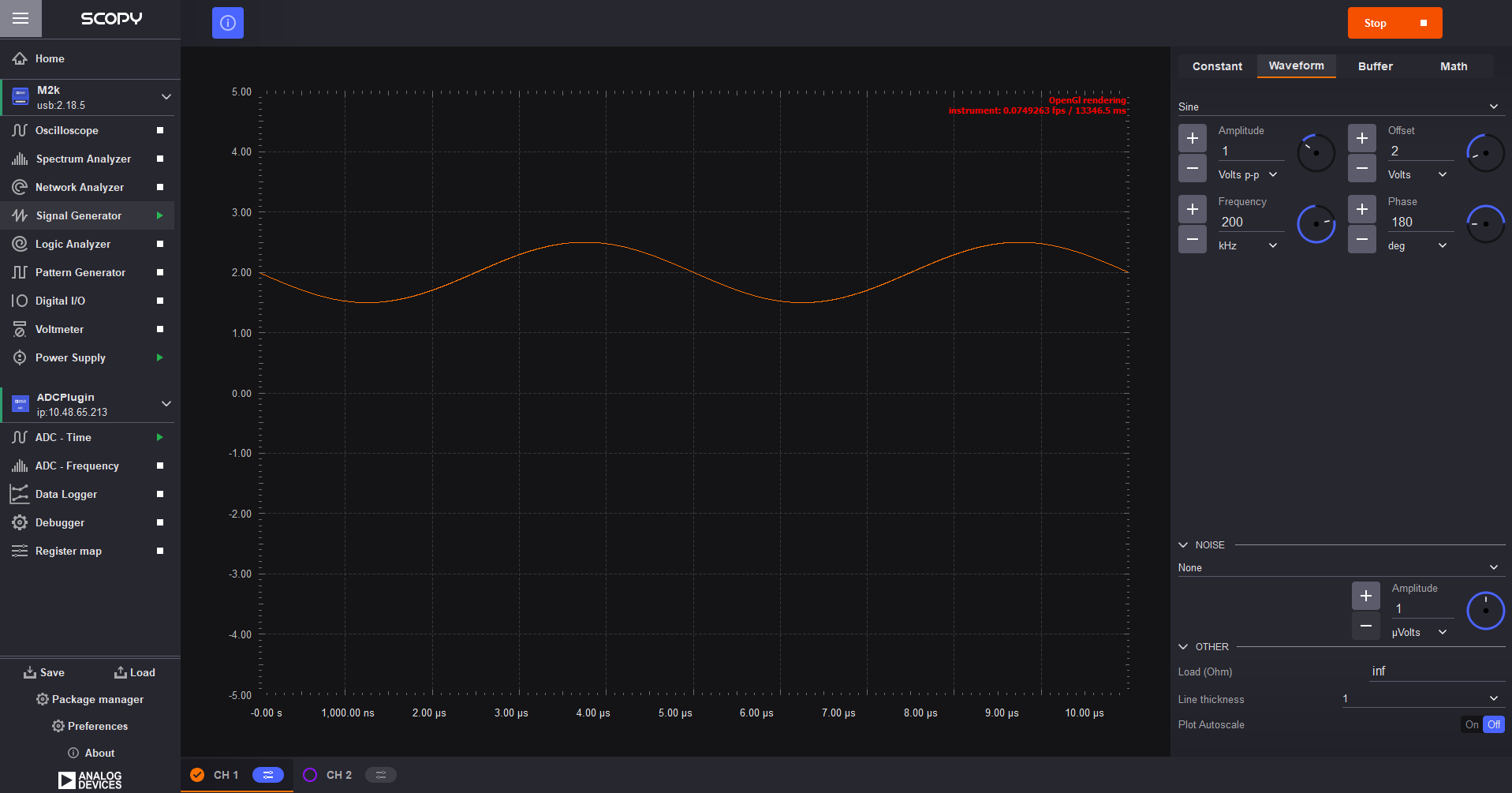
For testing we used an input signal with a frequency of 200kHz and an amplitude of 1V.
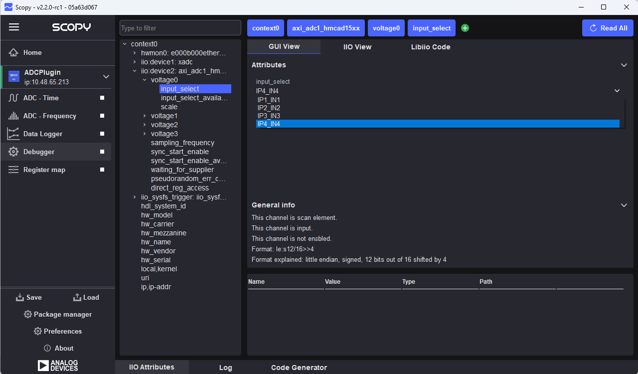
First we need to Select Debugger -> iio:device2: axi_adc_hmcad15xx and for each voltage go to input_select and select the port on which you want that channel to listen to
Scopy
Scopy is a cross-platform software toolbox for interfacing with ADI devices, enabling you to configure device parameters, visualize data, and perform advanced signal analysis.
Data capture
Time domain:
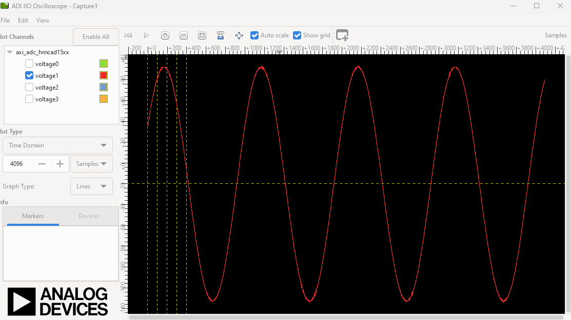
In the above figure we are using a Single Channel configuration.