Quickstart
The Quick Start Guide provides step by step instructions detailing how to set up the AD-FMCXMWBR1-EBZ board. The ADRV9009-ZU11EG RF-SOM and ADRV2CRR-FMC platforms will be used to demonstrate the appropriate board and cable connections.
The AD-FMCXMWBR1-EBZ is a kit of two boards connected with ribbon cables. The customer needs to plug the AD-FMCXMWBR1-EBZ module in an FMC slot on a carrier. The Protoplate Interface board should be mounted on a 32x32 X-Microwave Prototype plate, then connected by ribbon cables. At this point, the carrier board can be turned on and the setup can be used accordingly.
Important
The adjustable supplies are set by default to the maximum value.
Supported Carriers
The AD-FMCXMWBR1-EBZ is, by definition, an “FPGA mezzanine card” (FMC), which means it needs a carrier to plug into. In most carriers, the AD-FMCXMWBR1-EBZ board connects to the FMC LPC connector. The carrier setup requires power, ethernet (Linux), HDMI or display port connections.
In addition to this, the AD-FMCXMWBR1-EBZ has a RaspberryPi compatible pin header that allows connection to any RaspberryPi development system or the X-MW controller.
FMC Carrier Setup
A typical setup with ADRV9009-ZU11EG RF-SOM Complete Prototyping System is shown below.
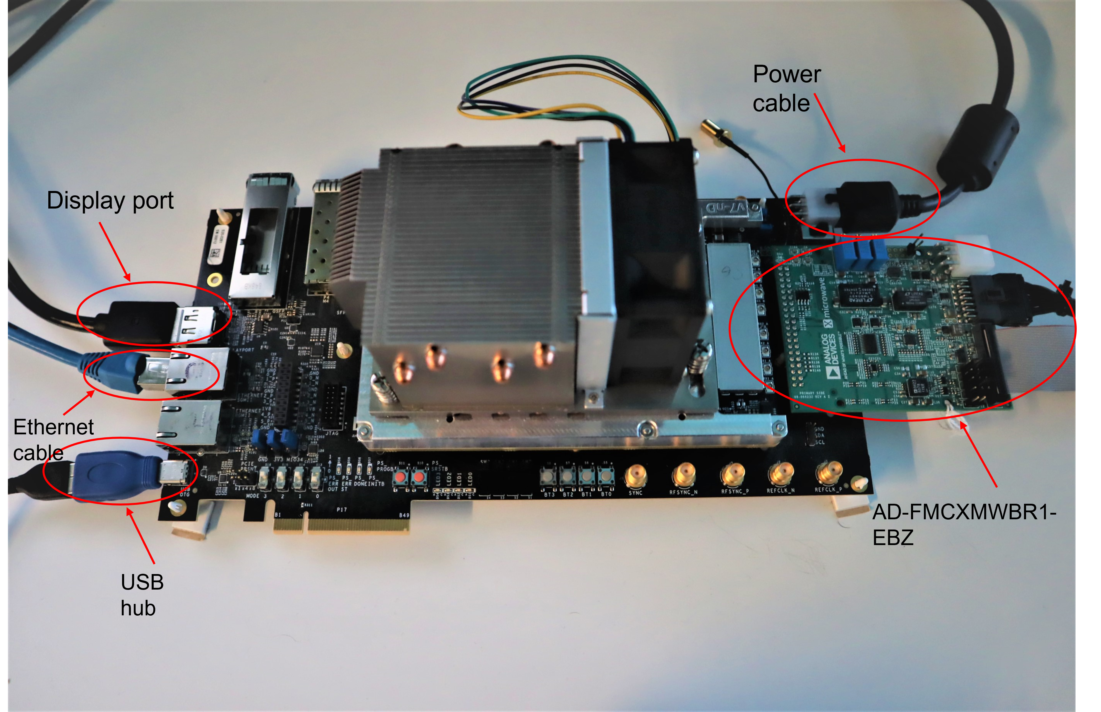
First, the ADRV9009-ZU11EG setup should be built. Please refer to the ADRV9009-ZU11EG Quick Start Guide.
ADRV2CRR-FMC should be powered and connected to a network with the ethernet cable.
The screen is connected to ADRV2CRR-FMC through a display port cable. If there is no image shown on the screen at the first boot, please refer to the guide.
Connect the USB OTG adapter and plug the USB Port Hub. In the Port Hub will be connected the keyboard and the QR code scanner.
Plug the AD-FMCXMWBR1-EBZ into the FMC connector of the ADRV2CRR-FMC.
Use the cables provided in the kit to connect the AD-FMCXMWBR1-EBZ to the desired setup.
X-MW Controller Setup
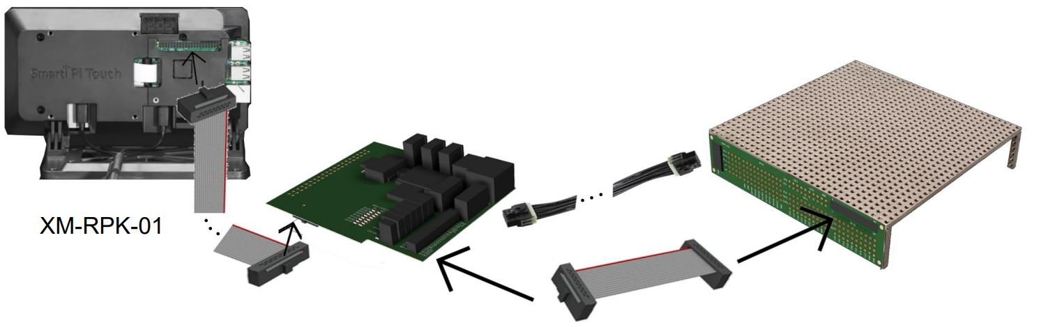
AD-FMCXMWBR1-EBZ has a pin header compatible with both the X-MW controller and the Raspberry Pi. It can be connected with a 40pin ribbon cable to the controller, and with the cables in the kit is connected to the X-Microwave setup.
Raspberry Pi Setup
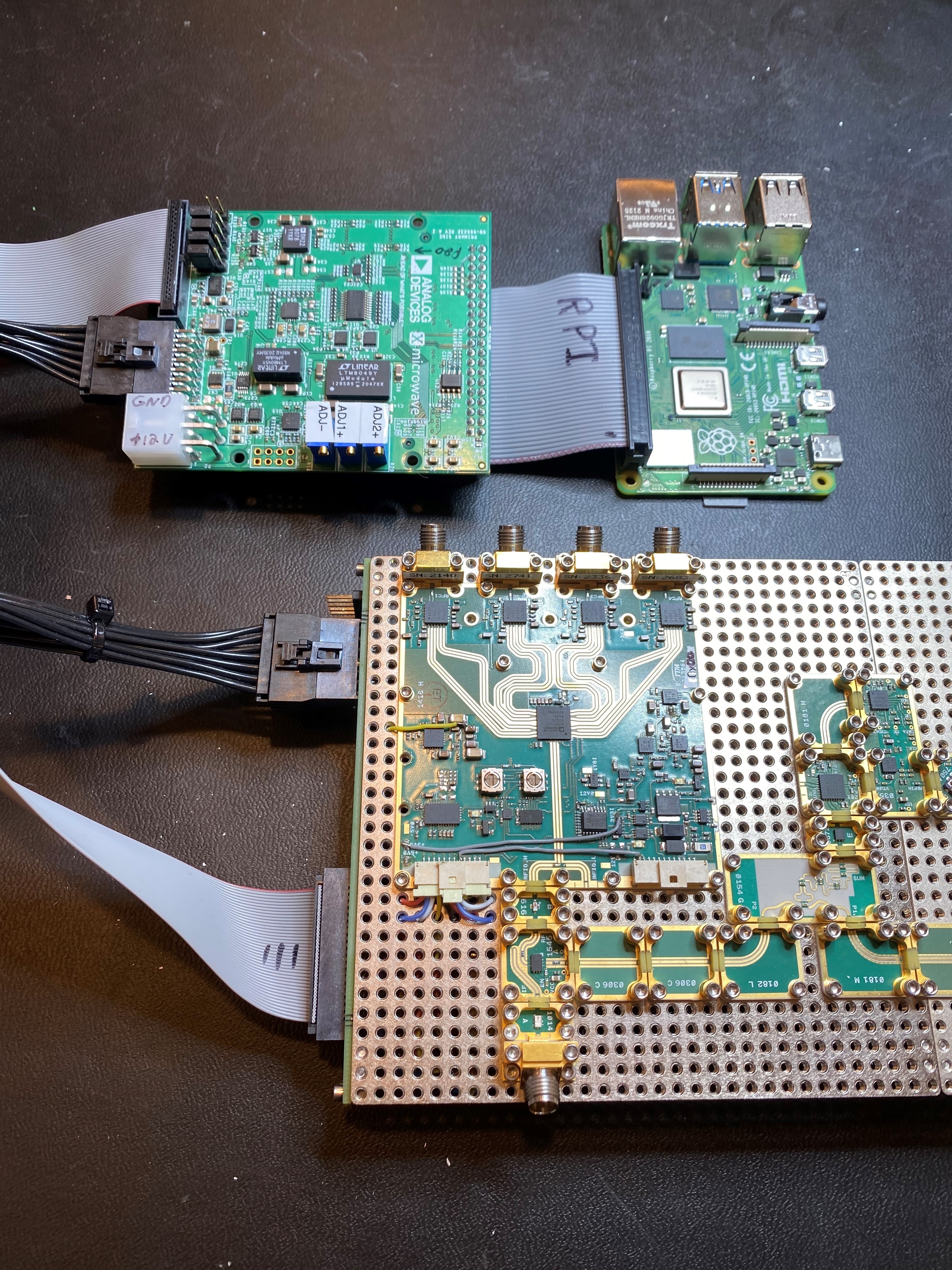
The AD-FMCXMWBR1-EBZ can be used with a standalone Raspberry Pi. It doesn’t have as many benefits as the setup with an FPGA board, but it can simplify the wiring and power supplies needed in an X-Microwave prototype.
Software
HDL Reference Design
The reference design uses SPI and I2C to interface with the AD-FMCXMWBR1-EBZ FMC bridge. The design is built upon ADI’s generic HDL reference design framework. More information about the framework can be found in the ADI Reference Designs HDL User Guide.
For more details regarding the digital interface, check the main ADRV9009ZU11EG HDL Reference Design.
In order to build the HDL design the user has to go through the following steps:
Confirm that you have the right tools (see Release notes)
Clone the HDL GitHub repository (see git)
Build the project (see build)
The device control and monitor signals are interfaced to a GPIO module. The SPI/I2C signals are controlled by a separate AXI based SPI/I2C core.
Download
Devicetree Support
Function |
File |
|---|---|
AD-FMCXMWBR1-EBZ Device Tree |
arch/arm64/boot/dts/xilinx/zynqmp-adrv9009-zu11eg-revb-adrv2crr-fmc-revb-jesd204-fsm-fmcbridge.dts |
An example of device tree for the AD-FMCXMWBR1-EBZ SPI/I2C/GPIO connections to different ADI devices:
#include "zynqmp-adrv9009-zu11eg-revb-adrv2crr-fmc-revb-jesd204-fsm.dts"

&fpga_axi {
    axi_i2c_1: i2c@83000000 {
        #address-cells = <1>;
        #size-cells = <0>;
        clock-names = "s_axi_aclk";
        clocks = <&zynqmp_clk 71>;
        compatible = "xlnx,axi-iic-2.0", "xlnx,xps-iic-2.00.a";
        interrupt-names = "iic2intc_irpt";
        interrupt-parent = <&gic>;
        interrupts = <0 90 IRQ_TYPE_LEVEL_HIGH>;
        reg = <0x0 0x83000000 0x1000>;
    };

    axi_i2c_2: i2c@83100000 {
        #address-cells = <1>;
        #size-cells = <0>;
        clock-names = "s_axi_aclk";
        clocks = <&zynqmp_clk 71>;
        compatible = "xlnx,axi-iic-2.0", "xlnx,xps-iic-2.00.a";
        interrupt-names = "iic2intc_irpt";
        interrupt-parent = <&gic>;
        interrupts = <0 91 IRQ_TYPE_LEVEL_HIGH>;
        reg = <0x0 0x83100000 0x1000>;
    };

    axi_spi_1: spi@84000000 {
        #address-cells = <1>;
        #size-cells = <0>;
        bits-per-word = <8>;
        compatible = "xlnx,xps-spi-2.00.a";
        reg = <0x0 0x84000000 0x1000>;
        fifo-size = <16>;
        interrupts = <0 92 IRQ_TYPE_EDGE_RISING>;
        num-cs = <0x8>;
        xlnx,num-ss-bits = <0x8>;
        xlnx,spi-mode = <0>;
    };

    axi_spi_2: spi@84500000 {
        #address-cells = <1>;
        #size-cells = <0>;
        bits-per-word = <8>;
        compatible = "xlnx,xps-spi-2.00.a";
        reg = <0x0 0x84500000 0x1000>;
        fifo-size = <16>;
        interrupts = <0 93 IRQ_TYPE_EDGE_RISING>;
        num-cs = <0x8>;
        xlnx,num-ss-bits = <0x8>;
        xlnx,spi-mode = <0>;
    };

    axi_gpio: gpio@86000000 {
        #gpio-cells = <2>;
        #interrupt-cells = <2>;
        clock-names = "s_axi_aclk";
        clocks = <&zynqmp_clk 71>;
        compatible = "xlnx,axi-gpio-2.0", "xlnx,xps-gpio-1.00.a";
        gpio-controller;
        interrupt-controller;
        interrupt-names = "ip2intc_irpt";
        interrupt-parent = <&gic>;
        interrupts = <0 9 4>;
        reg = <0x0 0x86000000 0x1000>;
        xlnx,all-inputs = <0x0>;
        xlnx,all-inputs-2 = <0x0>;
        xlnx,all-outputs = <0x0>;
        xlnx,all-outputs-2 = <0x0>;
        xlnx,dout-default = <0x00000000>;
        xlnx,dout-default-2 = <0x00000000>;
        xlnx,gpio-width = <0x20>;
        xlnx,gpio2-width = <0x20>;
        xlnx,interrupt-present = <0x1>;
        xlnx,is-dual = <0x1>;
        xlnx,tri-default = <0xFFFFFFFF>;
        xlnx,tri-default-2 = <0xFFFFFFFF>;
    };
};

&axi_i2c_1 {
    ad7291_1@2f {
        label = "ADC_I2C_1";
        compatible = "adi,ad7291";
        reg = <0x2f>;
    };
};

&axi_i2c_2 {
    ad7291_2@2f {
        label = "ADC_I2C_2";
        compatible = "adi,ad7291";
        reg = <0x2f>;
    };
};

&axi_spi_1 {
    ad5721r_1@0 {
        label = "DAC_SPI_1";
        compatible = "adi,ad5721r";
        reg = <0>;
        spi-max-frequency = <500000>;
    };
};

&axi_spi_2 {
    ad5721r_2@0 {
        label = "DAC_SPI_2";
        compatible = "adi,ad5721r";
        reg = <0>;
        spi-max-frequency = <500000>;
    };
};

&i2c_fmc {
    eeprom@52 {
        compatible = "at24,24c02";
        reg = <0x52>;
    };
};
SPI/I2C Device Access from Linux Userspace
analog@analog:/sys/bus/iio/devices $ ls -l
total 0
lrwxrwxrwx 1 root root 0 Feb 14 14:48 iio:device1 -> ../../../devices/platform/fpga-axi@0/84000000.spi/spi_master/spi1/spi1.0/iio:device1
lrwxrwxrwx 1 root root 0 Feb 14 14:48 iio:device2 -> ../../../devices/platform/fpga-axi@0/84500000.spi/spi_master/spi2/spi2.0/iio:device2
lrwxrwxrwx 1 root root 0 Feb 14 14:48 iio:device5 -> ../../../devices/platform/fpga-axi@0/83000000.i2c/i2c-11/11-002f/iio:device5
lrwxrwxrwx 1 root root 0 Feb 14 14:48 iio:device6 -> ../../../devices/platform/fpga-axi@0/83100000.i2c/i2c-12/12-002f/iio:device6
GPIO Control from Linux Userspace
analog@analog:/sys/class/gpio $ ls -l
total 0
-rwxrwx--- 1 root gpio 4096 Feb 14 14:48 export
lrwxrwxrwx 1 root gpio    0 Feb 14 14:48 gpiochip448 -> ../../devices/platform/fpga-axi@0/86000000.gpio/gpio/gpiochip448
-rwxrwx--- 1 root gpio 4096 Feb 14 14:48 unexport