IIO Oscilloscope
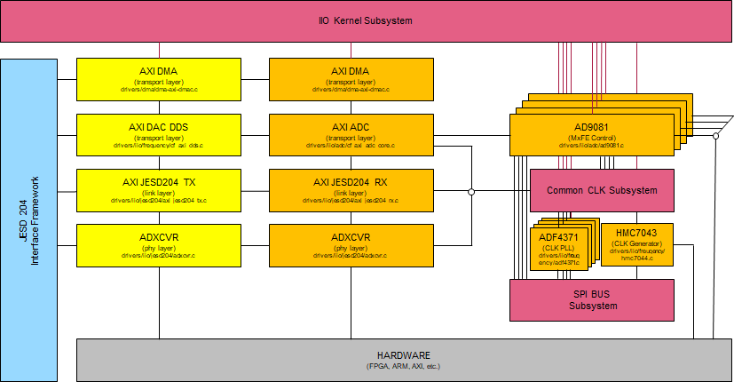
Software architecture overview
Tip
All programmable devices on the Quad MxFE platform are abstracted by IIO devices.
IIO Device |
Device Name |
Driver Documentation |
|---|---|---|
iio:device0 |
hmc425a |
|
iio:device1 |
adf4371-0 |
|
iio:device2 |
adf4371-1 |
|
iio:device3 |
adf4371-2 |
|
iio:device4 |
adf4371-3 |
|
iio:device5 |
hmc7043 |
|
iio:device6 |
axi-ad9081-rx-0 |
|
iio:device7 |
axi-ad9081-rx-1 |
|
iio:device8 |
axi-ad9081-rx-2 |
|
iio:device9 |
axi-ad9081-tx-3 |
|
iio:device10 |
axi-ad9081-rx-3 |
All these drivers feature a runtime API which can be controlled using IIO Oscilloscope, Libiio, etc. However some configuration is static and done inside the device tree. For Microblaze projects (VCU118) the device tree is built into the kernel image. Please see instructions on building custom kernel and devicetree images here:
IIO device axi-ad9081-rx-3 is special compared to the
axi-ad9081-rx-[0..2], since it controls the transport layer and therefore
features the IIO buffer. So all 16R data captures are controlled via this device,
while the other similar devices are there, to control the device instance specific
controls.
Also axi-ad9081-rx-3 aka. spi0.3 instantiates last, it therefore brings
up the JESD204 multi-link.
ad9081 spi0.0: JESD RX (JTX) Link1 in DATA, SYNC asserted, PLL locked, PHASE established, MODE valid
ad9081 spi0.0: JESD TX (JRX) Link1 0x0 lanes in DATA
ad9081 spi0.0: AD9081 Rev. 1 Grade 10 (API 0.7.4) probed
ad9081 spi0.1: JESD RX (JTX) Link1 in DATA, SYNC deasserted, PLL locked, PHASE established, MODE valid
ad9081 spi0.1: JESD TX (JRX) Link1 0x0 lanes in DATA
ad9081 spi0.1: AD9081 Rev. 1 Grade 10 (API 0.7.4) probed
ad9081 spi0.2: JESD RX (JTX) Link1 in DATA, SYNC deasserted, PLL locked, PHASE established, MODE valid
ad9081 spi0.2: JESD TX (JRX) Link1 0x0 lanes in DATA
ad9081 spi0.2: AD9081 Rev. 1 Grade 10 (API 0.7.4) probed
ad9081 spi0.3: JESD RX (JTX) Link1 in DATA, SYNC deasserted, PLL locked, PHASE established, MODE valid
ad9081 spi0.3: JESD TX (JRX) Link1 0xF lanes in DATA
ad9081 spi0.3: AD9081 Rev. 1 Grade 10 (API 0.7.4) probed
It’s expected that JRX, JTX status information may contain error status until
the last device probes and the Link is finally enabled. Device
axi-ad9081-tx-3 purely controls the TX transport layer, it therefore doesn’t
have any MxFE controls. Please use the iio_info command
to get an overview on what controls and capabilities exists.
IIO Oscilloscope application
The ADI IIO Oscilloscope is a cross platform GUI application, which demonstrates how to interface different evaluation boards from within a Linux system. The application supports plotting of the captured data in four different modes (time domain, frequency domain, constellation and cross-correlation). The application also allows to view and modify several settings of the development platform’s devices.
Documentation can be found here:
The MxFE AD9081 plugin is included in the official OSC release, which can be downloaded from here:
Instructions and overview
Start OSC from your application launcher or type
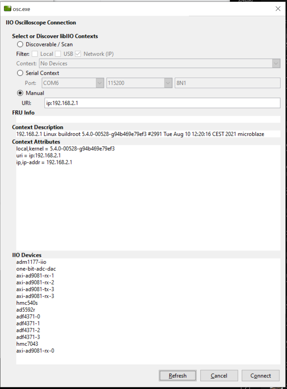
OSC.Enter the target IP address under
Remote Devicesand press theRefreshfollowed by theOkbutton.
The main capture window will appear
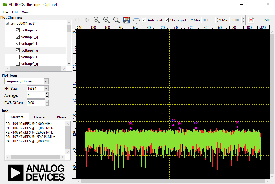
Use the scroll bar in the Plot Channel box to select the channels to display. The first eight channels correspond to the first device, second eight to the second device, etc.
Device to channel mapping (Rev. B/C platforms)
axi-ad9081-rx-0: spi.0.0 - MxFE U48
voltage0_i: (input, index: 0, format: le:S16/16>>0)
voltage0_q: (input, index: 1, format: le:S16/16>>0)
voltage1_i: (input, index: 2, format: le:S16/16>>0)
voltage1_q: (input, index: 3, format: le:S16/16>>0)
voltage2_i: (input, index: 4, format: le:S16/16>>0)
voltage2_q: (input, index: 5, format: le:S16/16>>0)
voltage3_i: (input, index: 6, format: le:S16/16>>0)
voltage3_q: (input, index: 7, format: le:S16/16>>0)

axi-ad9081-rx-1: spi.0.1 - MxFE U49
voltage4_i: (input, index: 8, format: le:S16/16>>0)
voltage4_q: (input, index: 9, format: le:S16/16>>0)
voltage5_i: (input, index: 10, format: le:S16/16>>0)
voltage5_q: (input, index: 11, format: le:S16/16>>0)
voltage6_i: (input, index: 12, format: le:S16/16>>0)
voltage6_q: (input, index: 13, format: le:S16/16>>0)
voltage7_i: (input, index: 14, format: le:S16/16>>0)
voltage7_q: (input, index: 15, format: le:S16/16>>0)

axi-ad9081-rx-2: spi.0.2 - MxFE U61
voltage8_i: (input, index: 16, format: le:S16/16>>0)
voltage8_q: (input, index: 17, format: le:S16/16>>0)
voltage9_i: (input, index: 18, format: le:S16/16>>0)
voltage9_q: (input, index: 19, format: le:S16/16>>0)
voltage10_i: (input, index: 20, format: le:S16/16>>0)
voltage10_q: (input, index: 21, format: le:S16/16>>0)
voltage11_i: (input, index: 22, format: le:S16/16>>0)
voltage11_q: (input, index: 23, format: le:S16/16>>0)

axi-ad9081-rx-3: spi.0.3 - MxFE U76
voltage12_i: (input, index: 24, format: le:S16/16>>0)
voltage12_q: (input, index: 25, format: le:S16/16>>0)
voltage13_i: (input, index: 26, format: le:S16/16>>0)
voltage13_q: (input, index: 27, format: le:S16/16>>0)
voltage14_i: (input, index: 28, format: le:S16/16>>0)
voltage14_q: (input, index: 29, format: le:S16/16>>0)
voltage15_i: (input, index: 30, format: le:S16/16>>0)
voltage15_q: (input, index: 31, format: le:S16/16>>0)
Important
In Frequency Domain view channels can be only enabled pairwise (I+Q).
And not more that 2 frequency plots can be enabled in the same window.
However multiple (independent) plot windows can be opened.
The plugin window
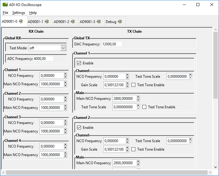
OSC will instantiate multiple notebook plugin tabs on the main window. One for
each device AD9081-X with an additional Debug plugin.
AD9081-3 again is special since it also has the controls for the TX transport
layer core (axi-ad9081-tx-3), and the HMC425 Digital Step Attenuator.
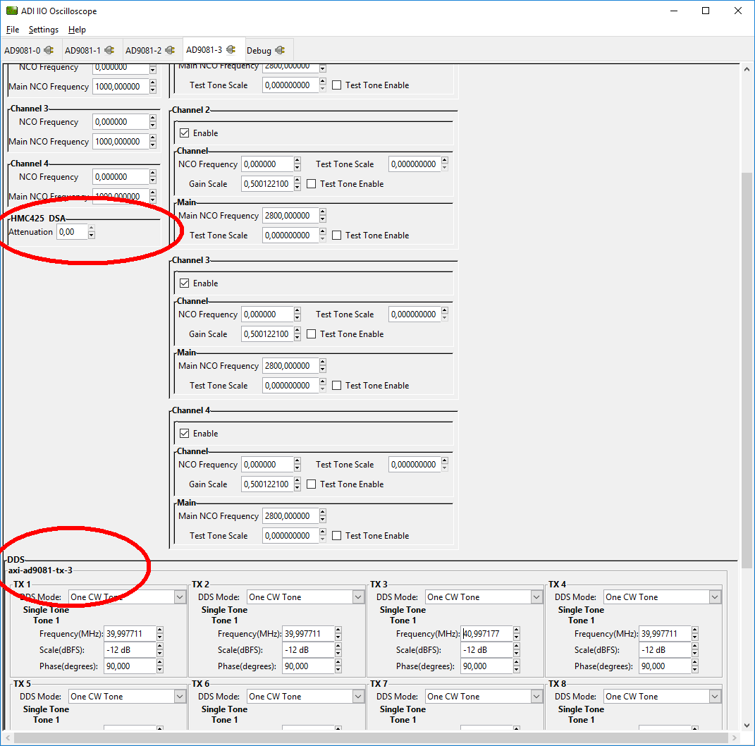
Loading custom waveform
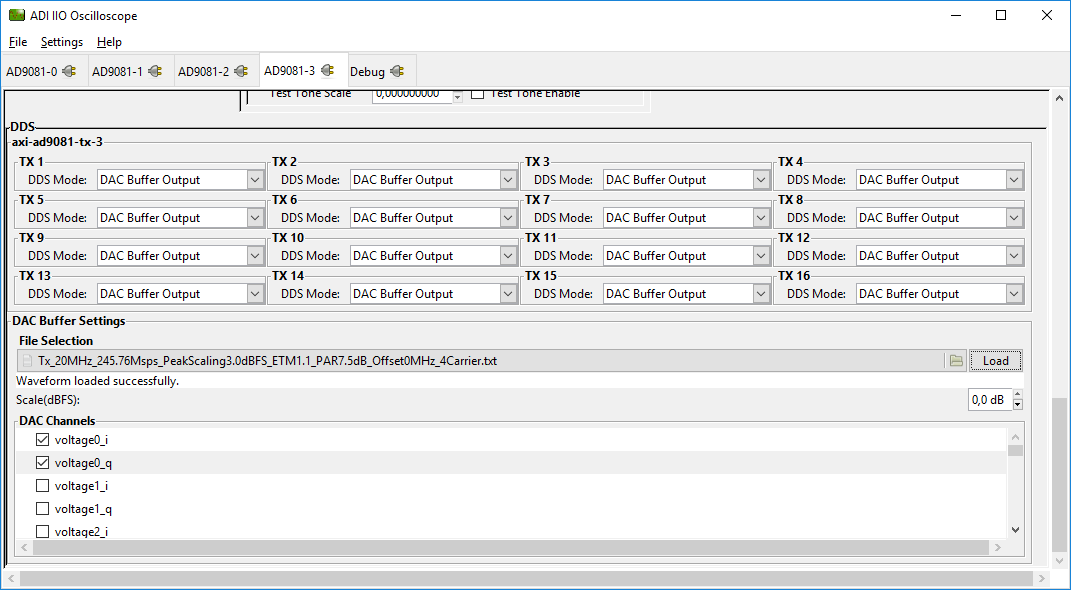
Set DDS mode to DAC Buffer Output, select a file hit Load button.
Optionally set a scale, and select the channels.
Tip
Please be aware that due to DDR3 memory bandwidth limitations only 2 or 4 can be enabled simultaneously.
The Debug Plugin
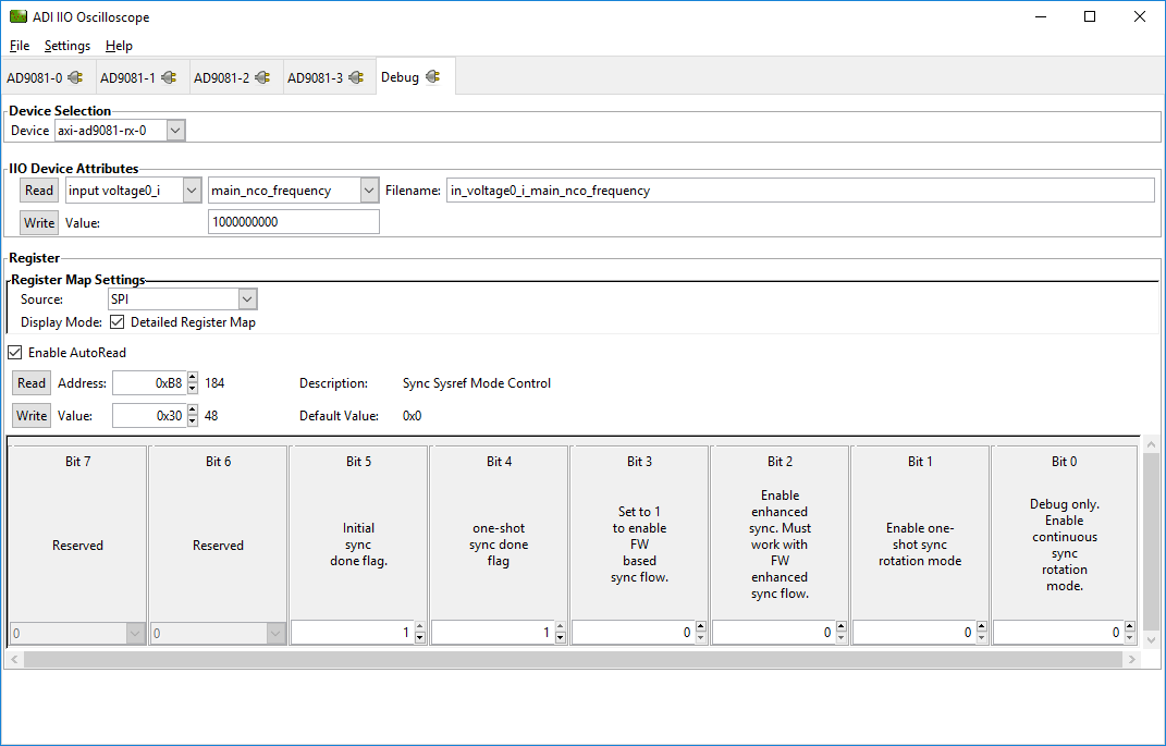
Under Device Selection, select the IIO device which should be
debugged/controlled.
In the IIO Device Attribute section, all device and channel attributes can be
read or written, including all attributes which are not handled by the
AD9081-X device plugin itself.
In the Register section select source SPI, check
Detailed Register Map and AutoRead, this will enable a complete AD9081
register view with description bitfields and dropdown options if available.
IIO devices axi-ad9081-tx-3 and axi-ad9081-rx-3 are again special, since
beside the SPI option they also can access the AXI_CORE register space of the
transport layer core.
Useful IIO commands
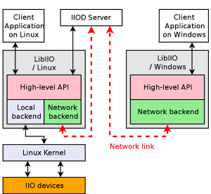
There are a few command line tools that are included with libIIO:
iio_info: dump the IIO attributesiio_attr: read and write IIO attributesiio_readdev: read an IIO buffer deviceiio_writedev: write an IIO buffer deviceiio_reg: read or write SPI or I2C registers in an IIO device (useful to debug drivers)
Note
See Cmd Line for detailed usage.
Important
All of these commands can be used local or remote
When using remote backend please install libiio for your platform.
Windows example
Download and install: Libiio v0.18 Windows installer
Open windows command prompt: cmd
Tip
unlike iio_info and iio_attr, iio_reg requires an environmental
variable IIOD_REMOTE to be set with the target IP address.
The names of the iio devices can be obtained using iio_attr command.
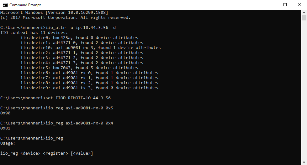
Example: Change main NCO frequency
~$
iio_attr -u ip:10.44.3.56 -i -c axi-ad9081-rx-3 voltage0_i main_nco_frequency 1200000000
dev 'axi-ad9081-rx-3', channel 'voltage0_i' (input), attr 'main_nco_frequency', value '1000000000'
wrote 11 bytes to main_nco_frequency
dev 'axi-ad9081-rx-3', channel 'voltage0_i' (input), attr 'main_nco_frequency', value '1200000000'
Further information
Further information about libiio and its usage can be found here:
About IIO: Libiio
API Documentation: libiio API
Libiio: Libiio
Libiio internals: libiio internals