EVAL-CN0410-ARDZ Shield
CN0410 is an Arduino compatible shield that is optimized for smart agriculture to control current passing through LED’s. The CN0410 is used along the the CFTL-LED Bar that has LED’s with specific wavelengths that plants utilize.
The circuit shown below is a complete 3-channel single-supply, 16-bit unbuffered voltage output DAC that maintains ±2 LSB integral and differential nonlinearity by utilizing a CMOS DAC. This circuit has a voltage to current conversion that controls the amount of current passing through an LED by using a MOSFET in its configuration. The circuit also has an isoSPI repeater that allows multiple boards to be controlled with a single master.
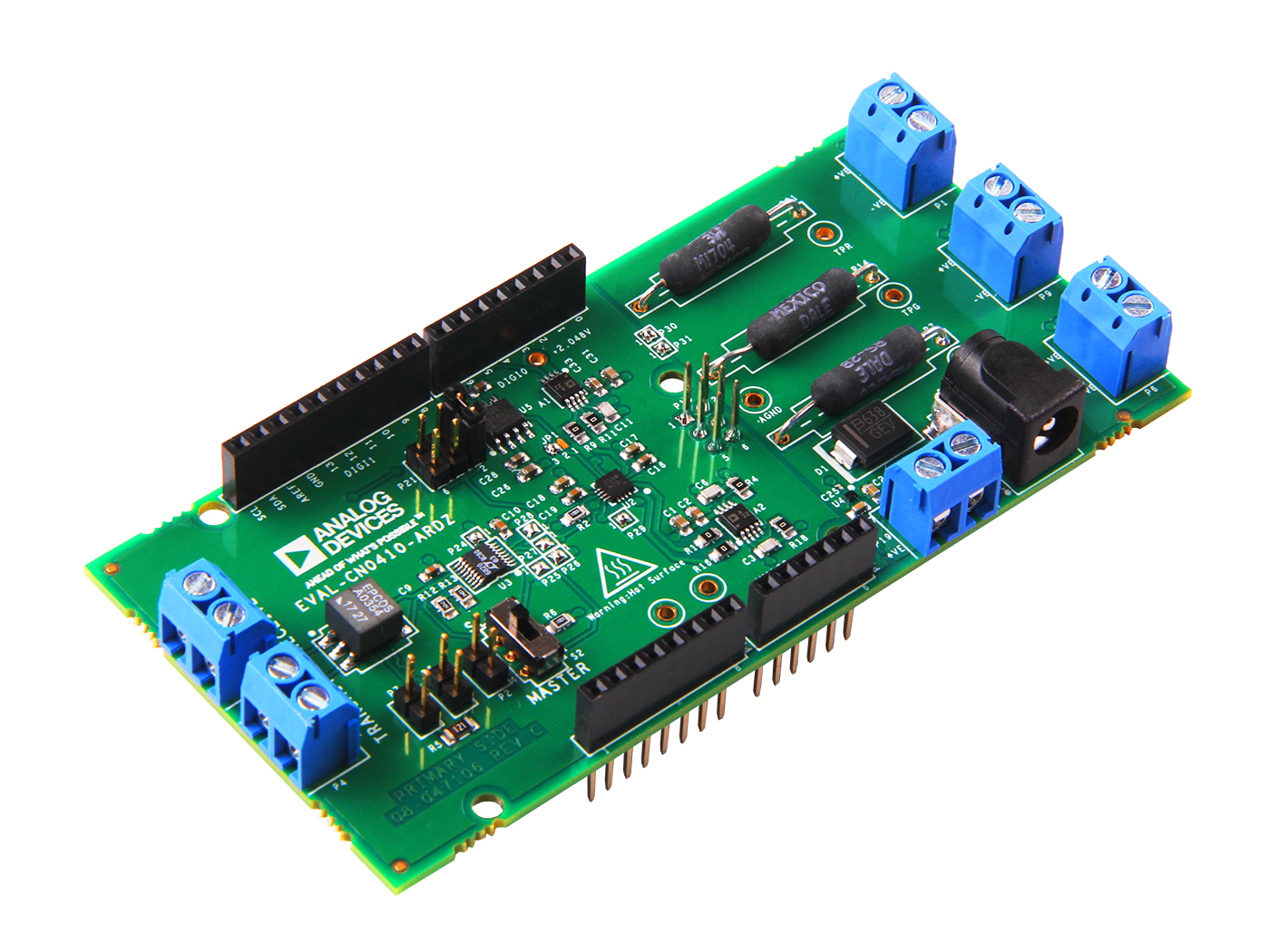
Connectors and Jumper Configurations
Chip Select
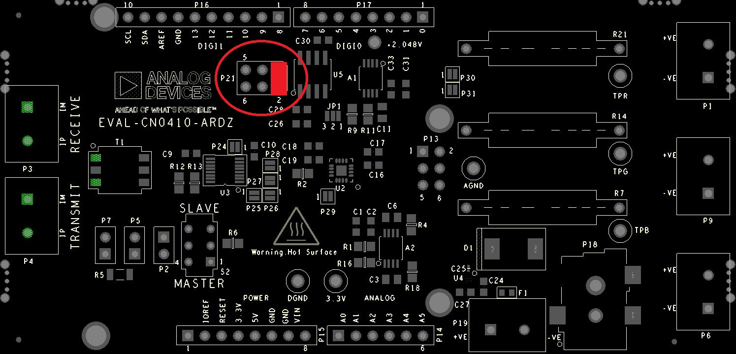
The chip select pin of the AD5686 is hardware configurable and routed to 3 general purpose I/O pins on the board. Use the table below to change the location of the chip select simply by moving the shunt on P21, and ensuring the software is configured the same way. By default the chip select is located on GPIO 8. This feature allows multiple boards using SPI communications protocol to be stacked on top of each other.
Chip Select (P21) |
GPIO (P16) |
|---|---|
Pins 1 & Pin 2 |
GPIO 8 |
Pins 3 & Pin 4 |
GPIO 9 |
Pins 5 & Pin 6 |
GPIO 10 |
LED Connectors
LED’s can be connected through connectors P1, P6 and P9 where each channel can independently source up to 1A of current using the 3 channels of the DAC. Pin 1 labelled as -ve of the terminal block is to be connected to the cathode of the LED and pin 2 labelled as +ve to be connected to the anode of the LED.
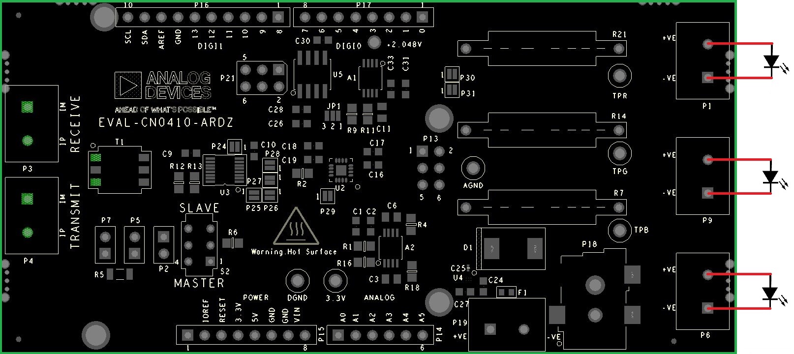
Recommended LED’s
Lumileds Red LED- LXM5-PD01
Lumileds Green LED- LXML-PM01-0080
Lumileds Blue LED- LXML-PB02
The circuit have been tested with CFTL-LED-BAR with up to 500mA of current which heats the board up to the rated temperature of the FR4 material used in the fabrication of the board.
Important
It is recommended to use cooling fans when using currents above 500mA per channel.
CFTL-LED-Bar Connectors
EVAL-CN0410-ARDZ |
CFTL-LED-BAR |
|---|---|
P1.1 |
P1.1 |
P1.2 |
P1.2 |
P6.1 |
P9.1 |
P6.2 |
P9.2 |
P9.1 |
P5.1 |
P9.2 |
P5.2 |
Transmit/Receive Connector
LT6820 allows for SPI communications protocol to be converted to pulses for long distance transmission. The transmit and receive connectors can be used to connect boards for up to 100 meters in length. Multiple boards can be connected with a single master using its multi-drop configuration, attaching board is series to each other.
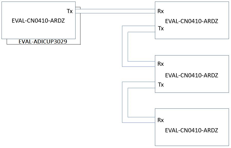
Master Mode Settings
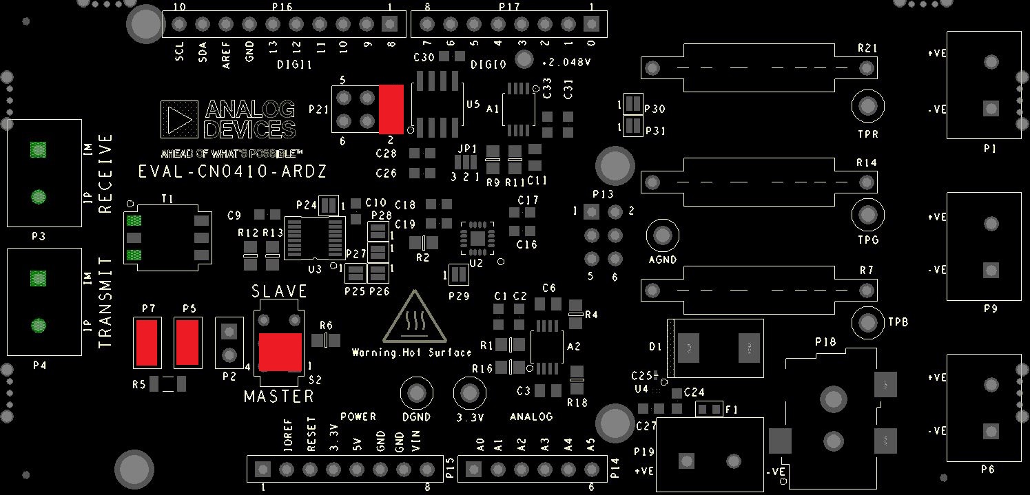
Refer to the table below to set the board as a master/transmitter:
P2 |
P5 |
P7 |
S2 |
|---|---|---|---|
Open |
Shorted |
Shorted |
Master Position |
Slave Mode Settings
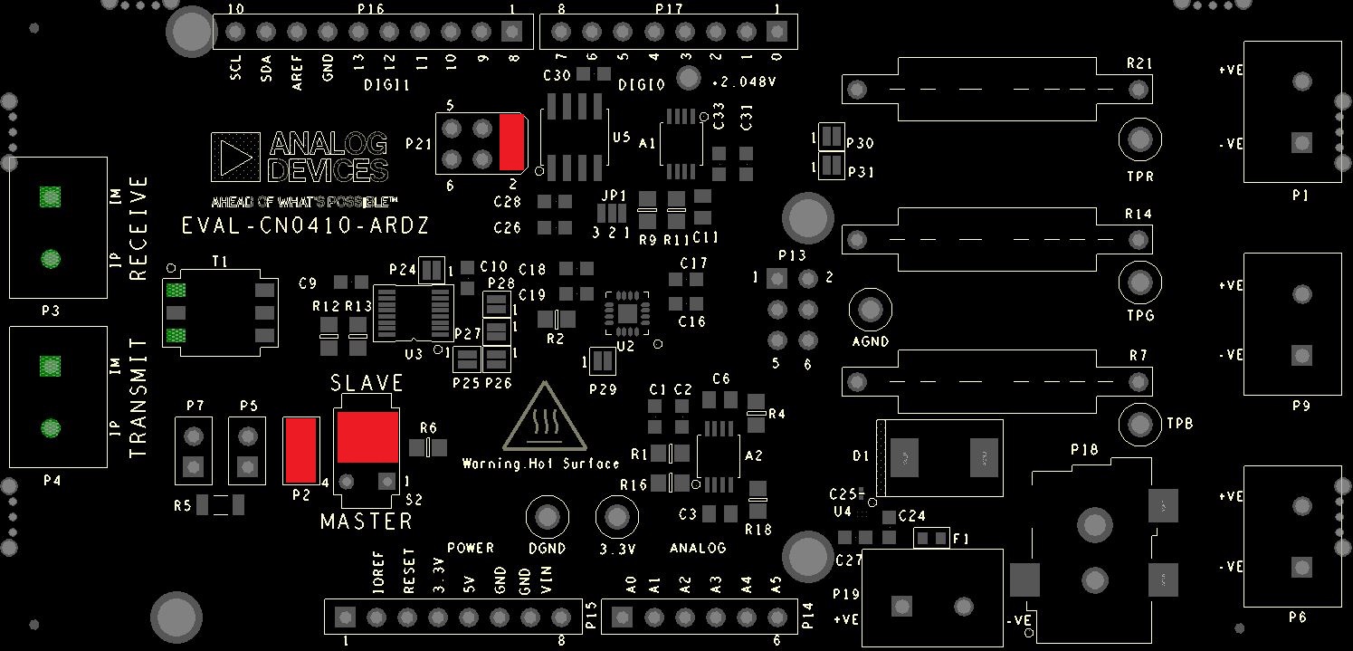
Refer to the table below to set the board as a slave:
P2 |
P5 |
P7 |
S2 |
|---|---|---|---|
Shorted |
Open |
Open |
Slave Position |
Important
A transformer or a pair of transformers are used to isolate the signals between the two LTC6820’s and must be terminated by a resistor. Only the master and the last slave on the transmission line must be terminated by shorting connectors P5 and P7
Schematic, PCB Layout, Bill of Materials
Download
EVAL-CN0410-ARDZ Design & Integration Files
Schematics
PCB Layout
Bill of Materials
Allegro Project
Software
Registration
Tip
Receive software update notifications, documentation updates, view the latest videos, and more when you register your hardware. Register to receive all these great benefits and more!
End of Document