Smart Greenhouse Application Demo
Overview
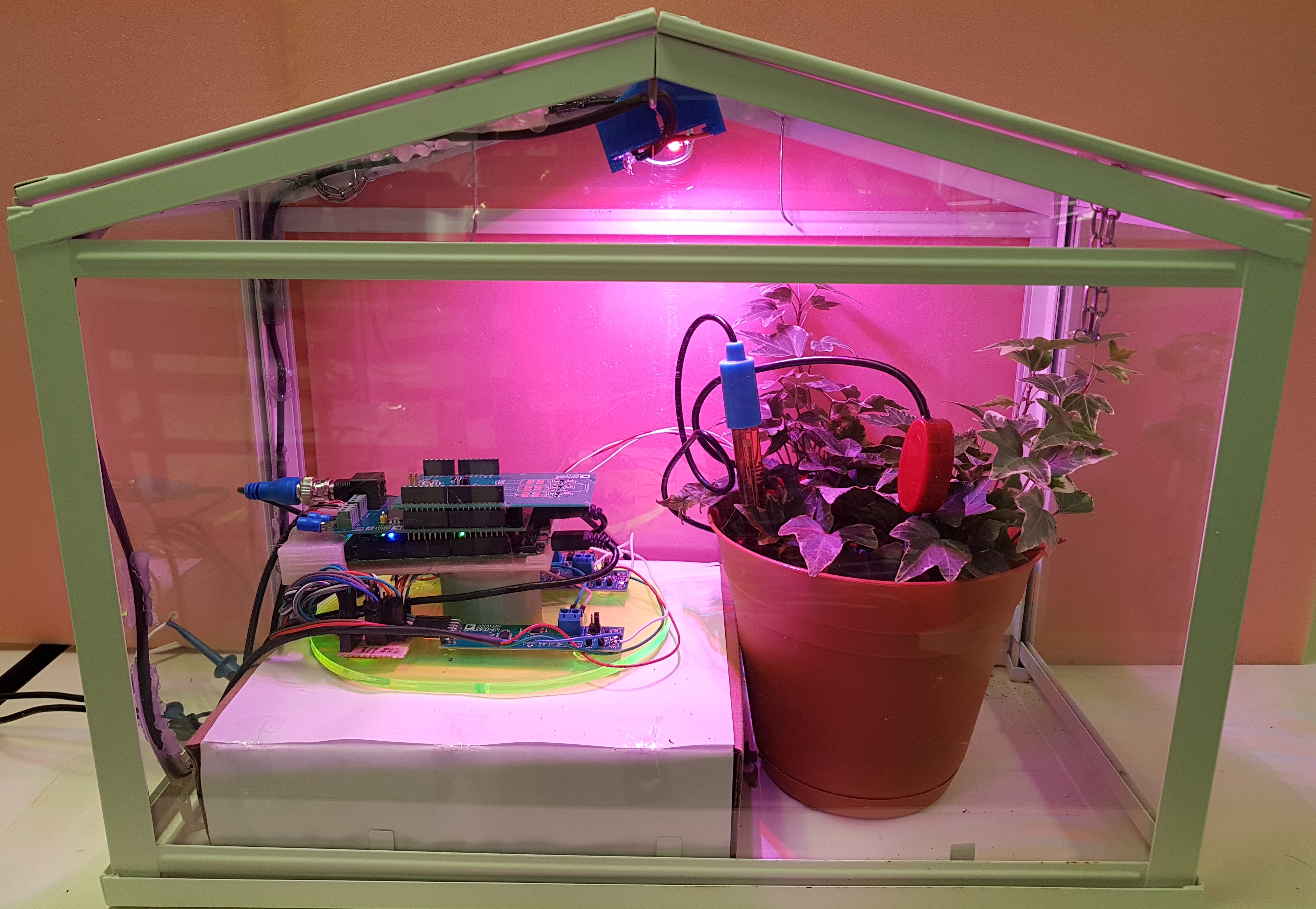
The demo concentrates on several important agriculture characteristics including soil moisture, soil pH with temperature compensation, as well as visible light recognition and control. These are three of the main sources of plant growth, and monitoring these are critical to the efficiency and optimization of the crop you are growing. CN0398 is a reference design that enables the demo to measure soil moisture, soil pH, and temperature. CN0397 allows the demo to measure the light intensities at certain visible light wavelengths that plants are sensitive to. CN0370 is a 16-bit LED current driver that controls the light intensity for a particular color LED, providing optimal lighting levels for the plants.
Smart Greenhouse demo showcases the capability of ADICUP360 in a fast prototyping environment in combination of 3 reference designs in two different form factors, Arduino form factor and PMOD form factor, to cater an applications in Smart Agriculture.
To learn more about the reference designs, please refer their individual circuit notes CN0370, CN0397 and CN0398.
Setup Requirements
Smart Greenhouse Demo Requirements
Boards/Hardware
Sensors
pH Probe with BNC termination type (Atlas Scientific pH probe)
3 Wire Moisture Sensor (VH400)
3 Wire PT100
627nm LED’s (LXM2-PD01-0050 used in demo)
540nm LED’s (LXML-PM01-0100 used in demo)
470nm LED’s (LXML-PB01-0040 used in demo)
Cables/Power
5V, 2A wall power supply(3 Pcs)
7V to 12V DC wall power supply
USB to micro USB cable
Software/Tools
How to setup Hardware
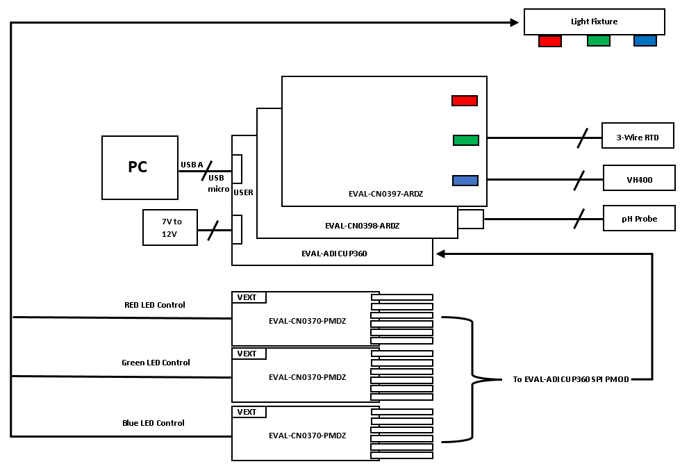
Functional Block Diagram
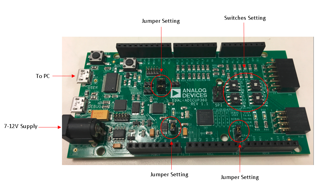
ADICUP360 Hardware Setup
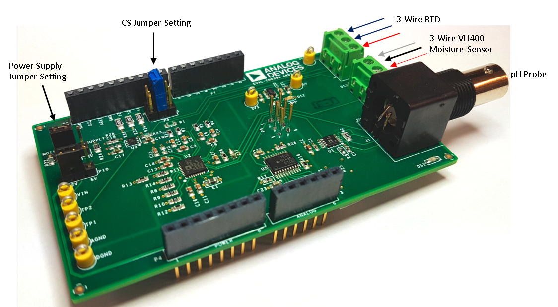
CN0398 Hardware Setup
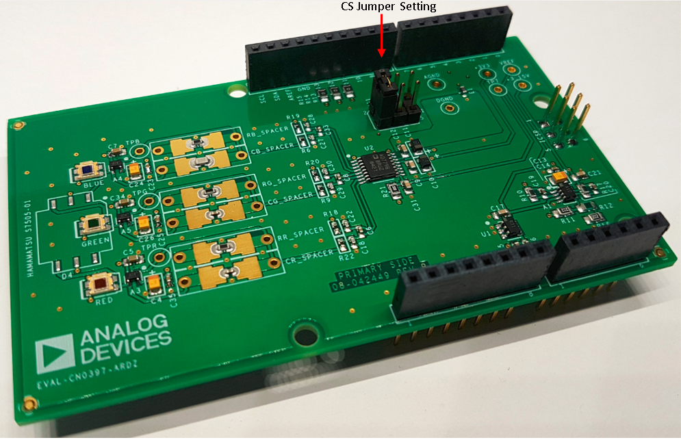
CN0397 Hardware Setup
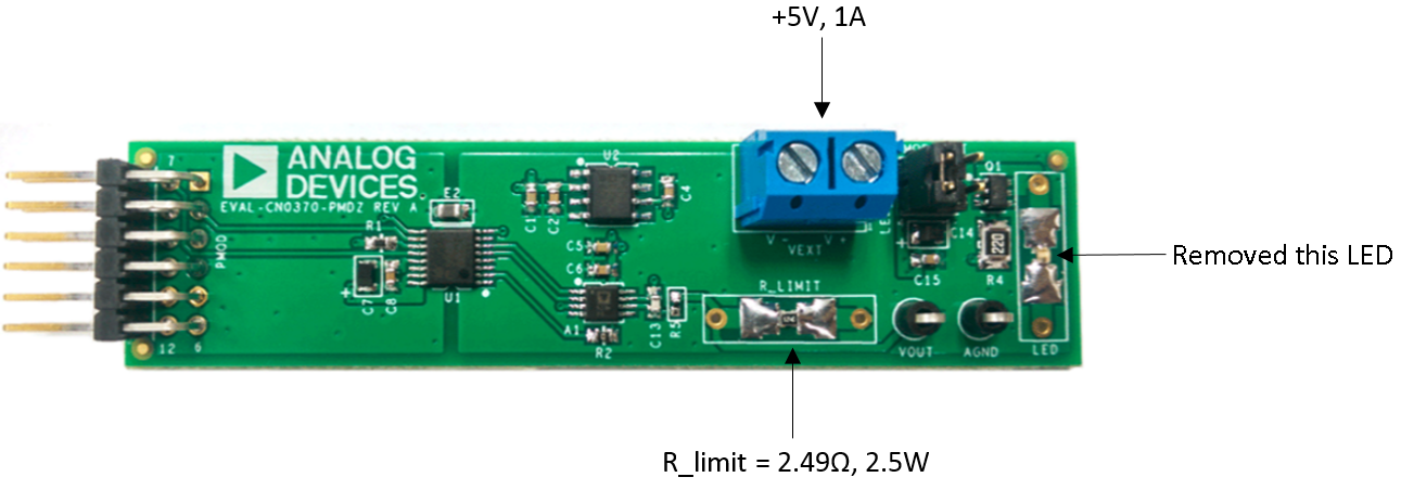
CN0370 Hardware Setup
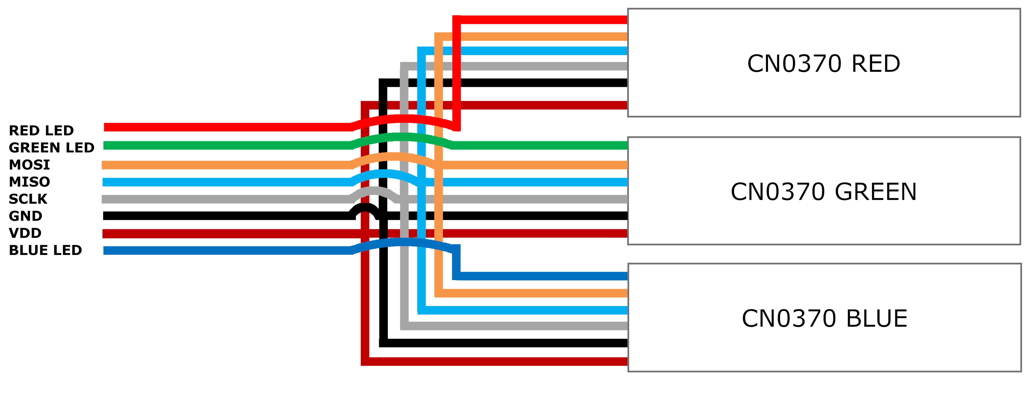
Chip select Assignment for each CN0370 boards are as follows:
CN0370 Control |
ADICUP360 Pin (P4) |
ADuCM360 Pin/Port |
|---|---|---|
Red LED |
7 |
P1.0 |
Green LED |
10 |
P2.2 |
Blue LED |
8 |
P1.1 |
MOSI |
2 |
P1.6 |
MISO |
3 |
P1.4 |
SCLK |
4 |
P1.5 |
GND |
5 |
DGND |
VDD |
7 |
DVDD |
Note
The demo used three CN0370 hardware routed on the same SPI bus with different chip selects and each hardware controls specific external LEDs which includes BLUE LED, GREEN LED and RED LED
Complete setup 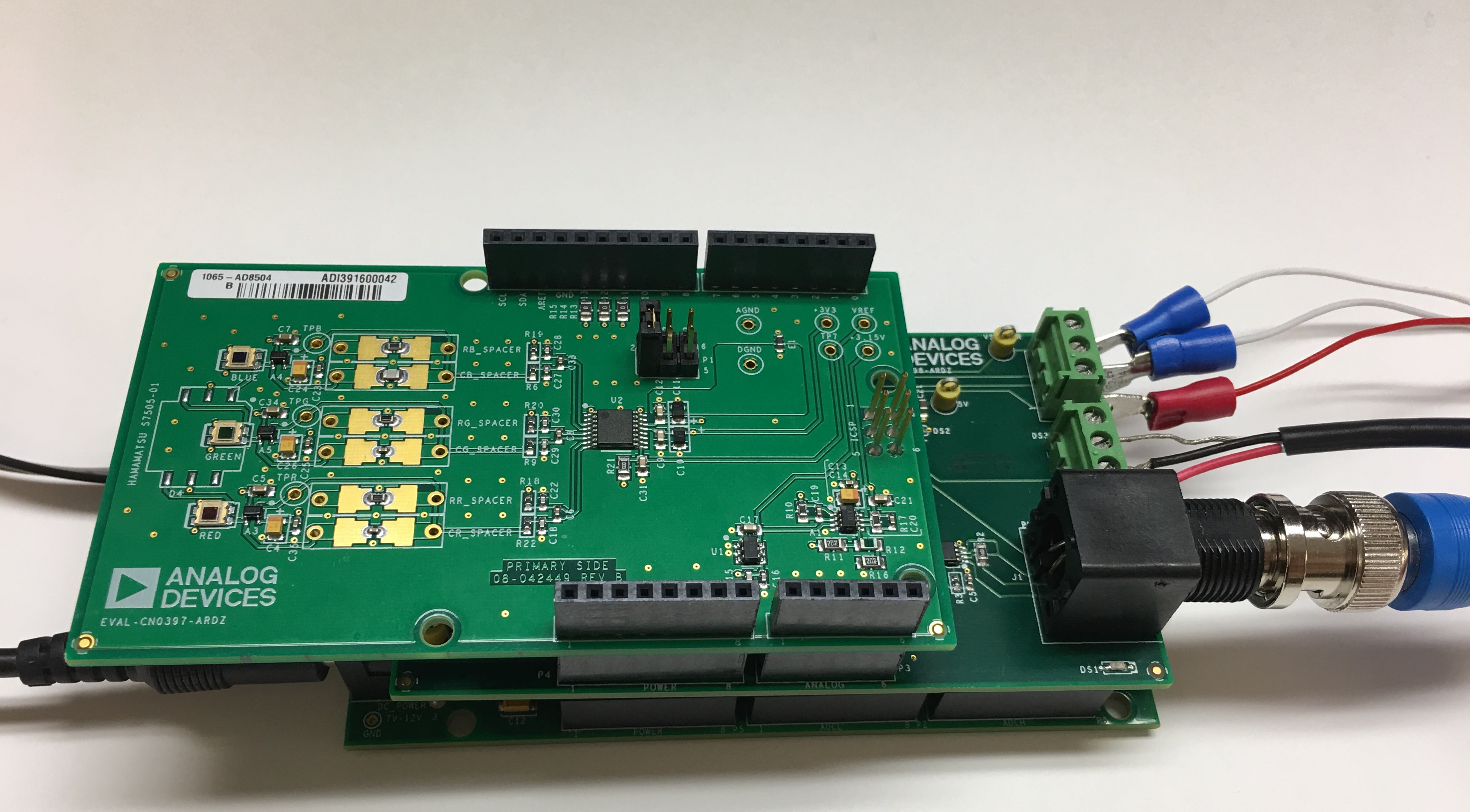 Hardware Connections as follows
Connect P3, P4, P6 and P7 connectors of EVAL-CN0398-ARDZ board on top of connectors P2, P5, P7 and P8 of the ADICUP360 board.
On top of the EVAL-CN0398-ARDZ board, connect the EVAL-CN0397-ARDZ to the Analog, Power , DigI1 and DigI0 connectors.
Route the SPI lines of three CN0370 boards to P4 (PMOD_SPI) of ADICUP360 board.
Apply 7-12V supply to DC barrel jack(P11) of ADICUP360 board
Connect USB micro to P14(DEBUG) of ADICUP360 using a micro USB to USB on the PC.
Drag and drop the Smart_Ag.bin file onto the MBED drive.Allow a few seconds for the program to download.
Disconnect the micro USB cable from P14(DEBUG) and connect the micro USB to P13(USER) of ADICUP360
Apply +5V, 1A supply to each CN0370 board
Software Description
The demo software is an integrated software of all the three reference designs which allows measurements of soil pH and moisture measurements with temperature compensation, as well as light detection and control.
The software allows calibration of the pH sensors and the photodiodes on the board for more accurate measurements. The LED’s can be controlled manually using the software and automatically by setting the desired intensity of each wavelength and using proportional control.
Obtaining the Source Code
There are two basic ways to program the ADICUP360 with the software for the Smart Greenhouse Demo.
Dragging and Dropping the .Bin to the MBED drive
Building, Compiling, and Debugging using CCES
Using the drag and drop method, the software is going to be a version that Analog Devices creates for testing and evaluation purposes. This is the EASIEST way to get started with the reference design.
Importing the project into CrossCore is going to allow you to change parameters and customize the software to fit your needs, but will be a bit more advanced and will require you to download the CrossCore toolchain.
The software for the ADuCM360_demo_Smart_Greenhouse demo can be found here:
Download
Prebuilt Smart Greenhouse Demo Bin File
Complete Smart Greenhouse Demo Source Files
Note
For more information on importing, debugging, or other tools related questions, please see the tools user guide.
How to use the Tools
The official tool we promote for use with the EVAL-ADICUP360 is CrossCore Embedded Studio. For more information on downloading the tools and a quick start guide on how to use the tool basics, please check out the Tools Overview page.
Importing
For more detailed instructions on importing this application/demo example into the CrossCore Embedded Studios tools, please view our How to import existing projects into your workspace section.
Debugging
For more detailed instructions on importing this application/demo example into the CrossCore Embedded Studios tools, please view our How to configure the debug session section.
Software Flow Diagram
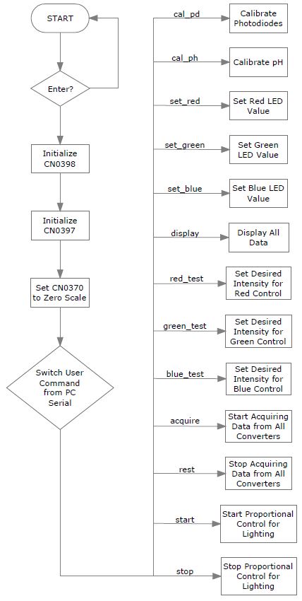
Upon start of the software, it will initialize all of the boards attached to the ADICUP360. CN0398 initialization will write all the settings to the IC’s on board, while CN0397 initialization will write the settings to the DAC registers. The CN0370 will be written with code zero to turn off all of the LED’s.
Once the initialization is complete, the program will now wait for a user command to execute the corresponding tasks.
Software Menu/Interaction
The following software section will help describe the steps you will need to go through when using the hardware and software together. There are some nationalizations and calibrations which must be done, and then some commands and instructions on how to use the software. Please read carefully to completely understand how to use the demo.
Initialization - Initialization will set up the hardware and sensors so that they can communication with the EVAL-ADICUP360 and all the setting and modes of the sensor boards are properly configured.
Calibrations - The light levels of the CN0397 need to be properly calibrated so that the value that is read by the system is accurate. The pH levels of the CN0398 have the option to be calibrated using known buffer solutions or can be skipped, and an ideal equation is used to determine the pH of the soil. The calibrated method will yeild more accurate results, but using the idea equation is faster.
Light Control Settings - User needs to set the amount of light that the plants are receiving, so they can optimially grow. The value set here is read by the CN0397 and then fed back into the CN0370 to either increase or decrease the light intensity. Values input into the Red, Green, Blue channels are all in units of LUX
Loop Setup - Select the desired mode of operation for the system.
Software Commands - Complete list of all available software commands, and what they do.
Initialization
Upon opening the serial terminal, you must press <Enter> to initialize program
This resets all peripherals and returns then to their default value
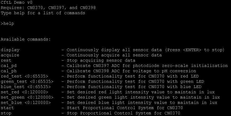
Typing “help” will show the list of commands
Calibration
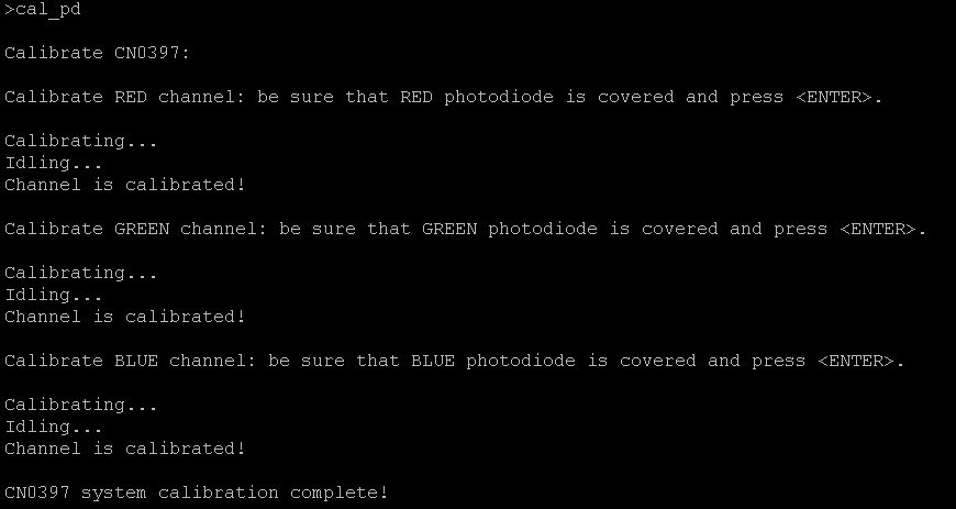
Calibrate the light sensors of the CN0397 by typing in “cal_pd”
This will prompt you to calibrate each of the sensors by covering the 3 photodiodes ensuring no light will pass through
Pressing enter will get you from one sensor to another until all of them are done
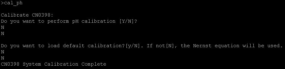
Calibrate the pH Sensor by typing in “cal_ph”
A question will pop up prompting to calibrate the pH sensor, press “n”.
A prompt will pop up to load default calibration. Press “n” to load the Nernst Equation. More information about direct measurement using Nernst equation where no calibration is performed can be found in CN0398 Circuit Note.
Pressing “y” on the calibration prompt will perform two point calibration by measuring the voltage of two buffer solutions, each with a known pH. The software includes NIST lookup tables for different pH buffer solutions and includes the pH temperature corrected pH values from 0°C to 95°C.For more information about pH two point calibration, visit CN0398 Circuit Note.
Light Control Settings
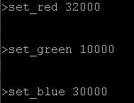
Type the command “set_red value” and press enter
Replace value with whole number from 0 to 120000
This will set the desired intensity
Type the command “set_green value” and press enter
Replace value with whole number from 0 to 120000
This will set the desired intensity
Type the command “set_blue value” and press enter
Replace value with whole number from 0 to 120000
This will set the desired intensity
Loop Setup
Type the command “acquire”
This will get all the boards to read data from its converters
Only type in “rest” if you want to stop acquisition
Type the command “start”
This will get the automatic control of the LED’s running to dial in to the set desired light intensity
Only type “stop” if you want to stop the proportional control
Type the command “display”
This will show all the processed data (pH, temp, moisture and light intensity) that has been acquired from the converters.
To exit and stop the display press enter
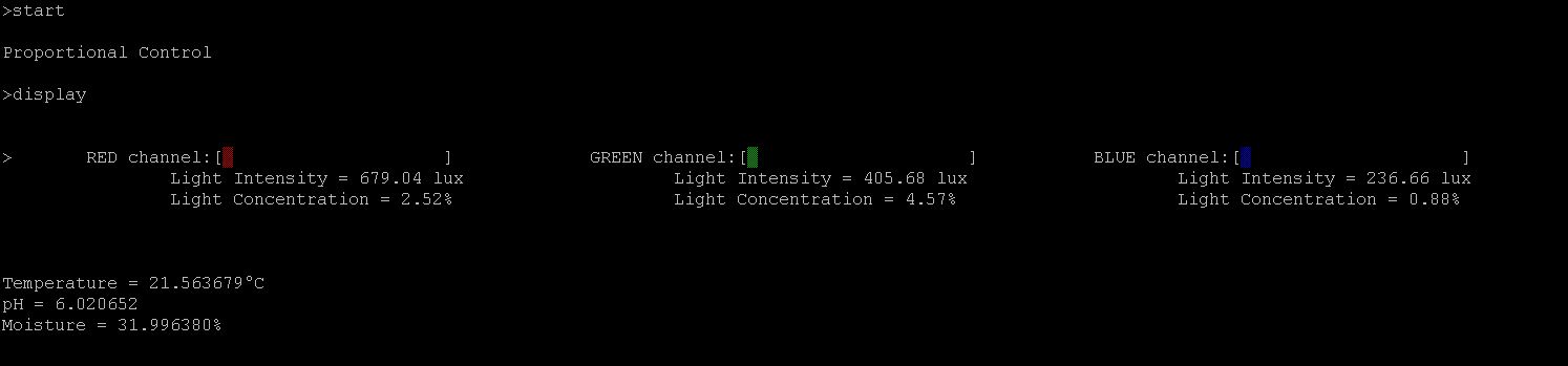
The demo should be running automatically displaying all the values and running its control automatically.
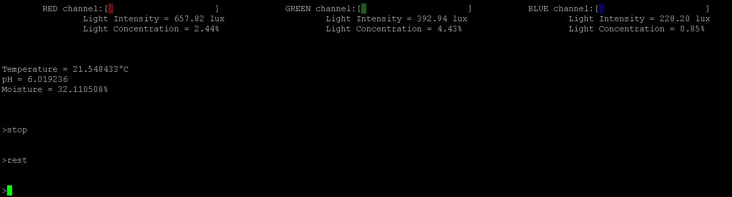
To exit the loop control
Stop the display by pressing enter
Stop the proportional control by typing the command “stop”
Stop acquisition by typing the command “rest”
Software Commands
Command |
Parameter to Pass |
Function/Description |
Example Command (if needed) |
|---|---|---|---|
display |
|
Continuously display all sensor data (Press <ENTER> to stop) |
|
acquire |
|
Continuously acquire all sensor data |
|
rest |
|
Stop acquiring sensor data |
|
cal_pd |
|
Calibrate CN0397 ADC for photodiode zero-scale initialization |
|
cal_ph |
|
Calibrate CN0398 ADC for voltage to pH conversion |
|
red_test |
(0-65535) |
Perform functionality test for CN0370 with red LED |
“red_test 35412” |
green_test |
(0-65535) |
Perform functionality test for CN0370 with green LED |
“green_test 4096” |
blue_test |
(0-65535) |
Perform functionality test for CN0370 with blue LED |
“blue_test 19754” |
set_red |
(0-120000) |
Set desired red light intensity value to maintain in lux |
“set_red 88000” |
set_green |
(0-120000) |
Set desired green light intensity value to maintain in lux |
“set_green 26500” |
set_blue |
(0-120000) |
Set desired blue light intensity value to maintain in lux |
“set_blue 115000” |
start |
|
Start Proportional Control System for CN0370 |
|
stop |
|
Stop Proportional Control System for CN0370 |
Serial Terminal/Output
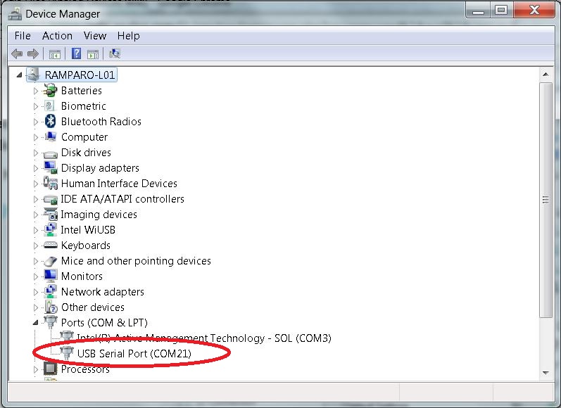
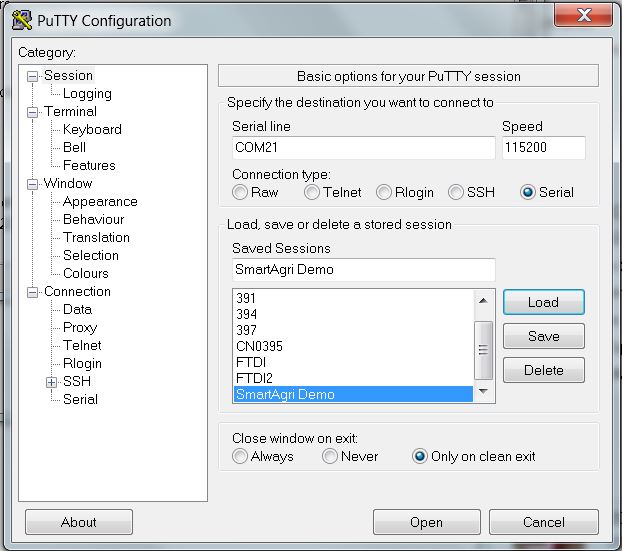 In puTTy cofiguration, select serial as the connection type with a baud rate of 115200. Select the correct COM port by checking it in your device manager.