Raspberry Pi User Guide
Setting up the system
Required hardware
Raspberry Pi The system was tested on Raspberry Pi3 Model B V1.2 and Raspberry Pi 4. It can work on other models that have a CSI camera interface input.
Raspberry Pi 5V power supply
To run the system in standalone mode, besides the accessories that are provided in the AD-96TOF1-EBZ box you’ll need an additional HDMI cable to connect to a monitor and a USB keyboard and mouse
RPi camera cable for connection between RPi and AD-96TOF1-EBZ
Modifying the AD-96TOF1-EBZ to work with the RPi
For the AD-96TOF1-EBZ rev.B to work with the RPi the following changes must be made on the camera board:
short pins 2 and 3 on JP1. JP1 is located underneath the laser board so the laser board must be first detached from the camera board to have access to this solder jumper
short R98 and R109
move the S1 switch to position 1 - to the dot on the switch
For the AD-96TOF1-EBZ rev.C to work with the RPi the following changes must be made on the camera board:
move the S1 switch to position 1 - to the dot on the switch
set the S5 switch 1 to OFF and all the other S5 switches to ON
Power on sequence
Plug the SD card into the Raspberry Pi SD card slot. To benefit from the most recent software updates it is highly recommended to update the SD card with the latest SD card image
Connect the HDMI cable from the monitor to the Raspberry Pi HDMI connector
Connect the RPi camera cable between the RPi and the P1 connector of the ToF board
Connect a USB mouse and keyboard to the Raspberry Pi. It’s possible to use either a mouse & keyboard combo or a separate mouse and keyboard
AD-96TOF1-EBZ rev.B
connect the I2C1 of the Raspberry Pi to AD-96TOF1-EBZ development kit. Please use jumper wires and the table below.
Raspberry Pi GPIO Header (J8) |
AD-96TOF1-EBZ pin header (P4) |
|---|---|
Pin 3 (SDA) |
Pin 17 |
Pin 21 |
|
Pin 5 (SCL) |
Pin 15 |
Pin 19 |
take care that the jumper wire connected to RPi header Pin 3 must be split in two and routed to both Pin 17 and Pin 21 on camera PCB. The same for SCL wire
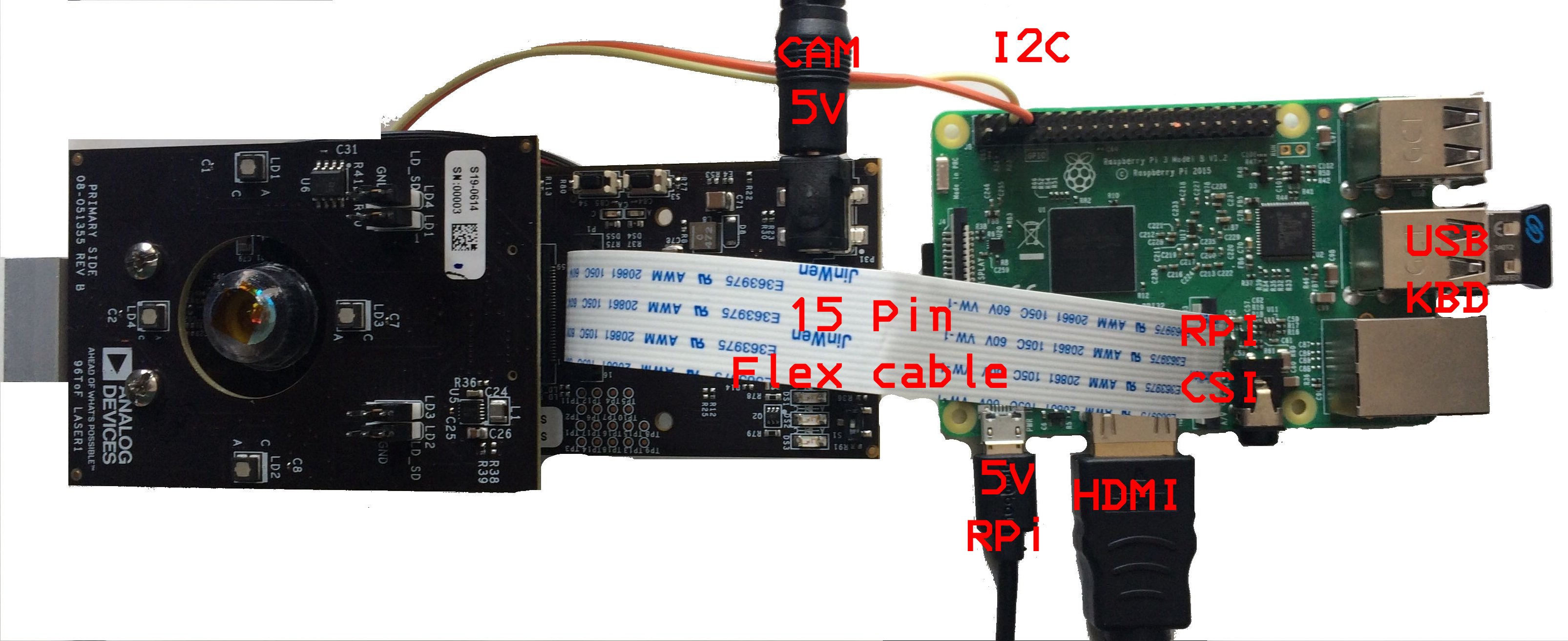
AD-96TOF1-EBZ rev.C
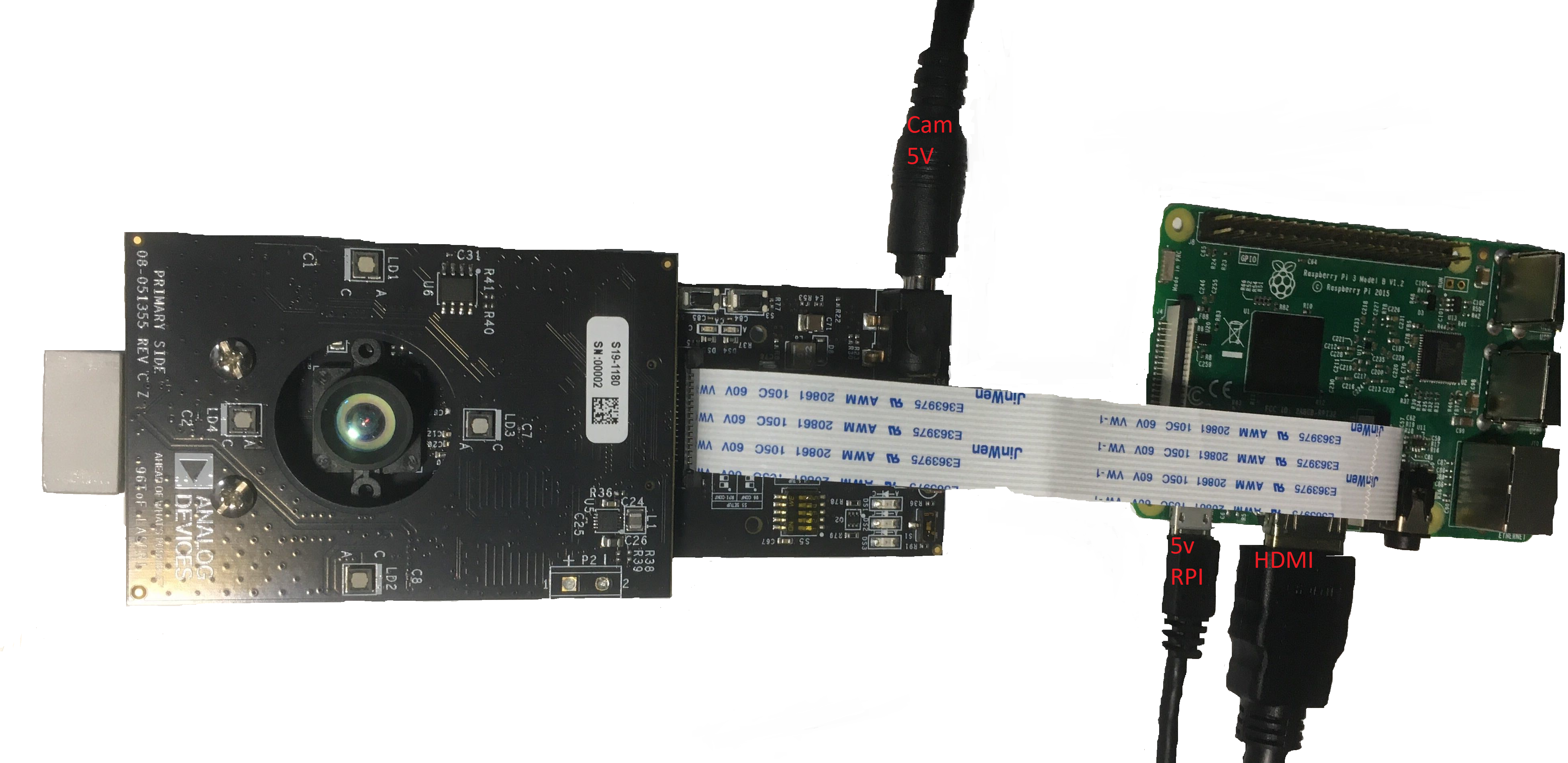
connect the 5V power supply to the camera board and set the camera power switch S2 to on. Once the camera board is powered up the DS1 LED will turn on
connect the 5V power supply to the Raspberry Pi. Once power is connected to the Raspberry Pi the system will boot the Linux OS from the SD card.
Power off sequence
Open a terminal and type sudo poweroff. This will safely power off the Raspberry Pi and ensure that the SD card is properly unmounted
remove the 5V supply from the Raspberry Pi
Set the camera board power switch to off
Troubleshooting
Linux does not boot
The SD card is corrupted and this prevents the system from booting. Reflash the SD card with the SD card image.
Running the evaluation application
Once Linux boots you’ll see on the HDMI monitor the Linux desktop and on the top left corner a shortcut to the evaluation application. Double clicking on the icon will start the evaluation application. A console window will open to show the application’s status and, after a few seconds, the evaluation application GUI will be displayed.
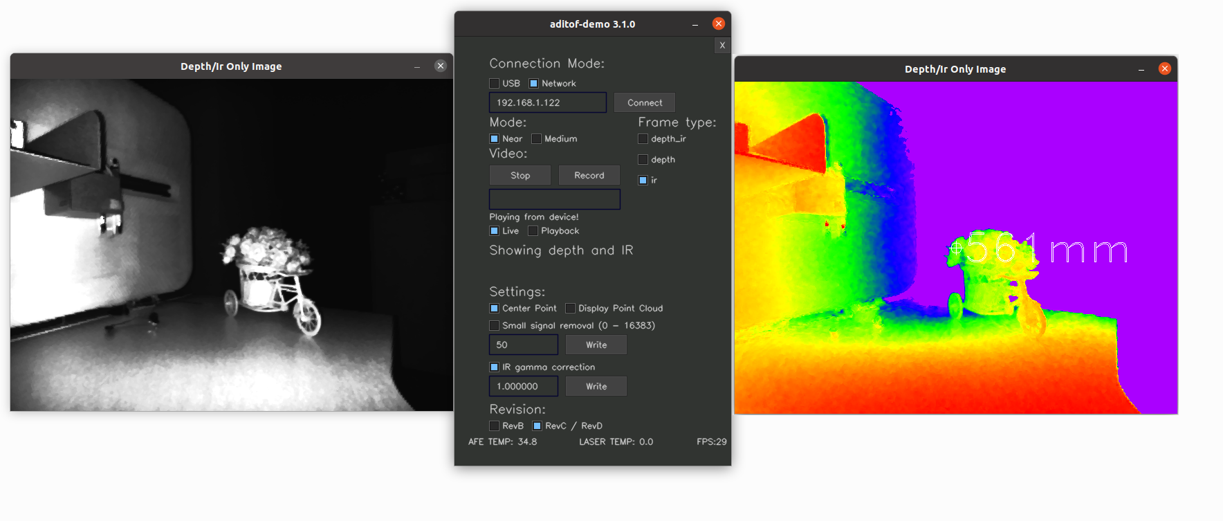
When starting the application, a terminal window will open to display status messages (also warning and error messages, in case there are any issues). Shorty the main window will show up.
The evaluation application allows to do live streaming of depth and IR data as well as recording the depth and IR data and playing back from a file. The depth data is displayed as a color map ranging from warm to cold colors as the distance from the camera increases. A point in the middle of the depth image shows the distance in mm to the target.
There are 3 operating modes that determine the range of the system:
Near - 25cm to 80cm
Medium - 30cm to 4.5m (Rev.B: 80cm to 3m)
Far - 300cm to 600cm
When in a certain operating mode the system will measure distances outside of the mode’s range but those will not be accurate.
The system is factory calibrated to achieve high accuracy in all the operating modes for indoor environments. It is possible to recalibrate the system for your specific operating conditions by using the calibration procedure and tools provided here.
The evaluation application also displays the temperature in deg C of the camera (AFE) and laser boards as read from the temperature sensors installed on each board.
The framerate at which data is acquired from the system is constantly updated on the GUI. The camera board outputs data at 30 frames per second (fps), but due to USB connection limitations, the host PC acquires the frames at a lower rate.
Enabling the point cloud display in aditof-demo
The demo application has the capability to display a point cloud image if it detects an OpenCV module called viz.
Unfortunately OpenCV does not provide binaries for this module so a manual build is needed. The steps required to install OpenCV and include it in the project are presented here: Windows Linux
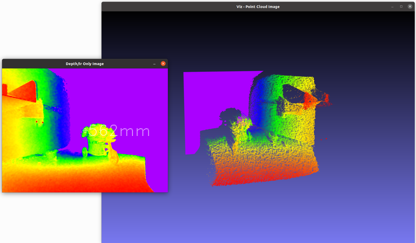
If aditof-demo finds all the OpenCV required modules a button in the interface will allow you to display the point cloud. By toggling the button a separate window will appear.
Important
Due to the limited computation speed of DragonBoard410c it is recomended to enable the point cloud only in the desktop sdk
Troubleshooting
The demo application hangs after closing the main window
Due to some limitations the application always hangs if it is closed using the regular X button from the window top bar (title bar). To avoid this unpleasant hang, we’ve made available a second X button in the top right corner right above the title bar that can be used to safely close the demo application. We hope this to be a temporary workaround.