EVAL-CN0416-ARDZ Shield Overview
CN0416 is an isolated and non-isolated RS-485 transceiver board which allows easy implementation of asynchronous serial (UART) data transmission between multiple Arduino form factor systems or nodes, especially over long distances. The circuit uses the ADM2682E RS-485 transceiver for isolated communications and the LTC2865 for non-isolated RS-485 communications. Both can be configured to either full-duplex or half duplex operation and with open or terminated transmission lines. The circuit has on-board RJ-45 ports which allows the use of the common CAT5 cable for fast physical wiring of nodes. The termination resistance is catered by default to the CAT5 cable characteristic impedance of 100 ohms but can be configured to support the standard RS485 cable impedance of 120 ohms. The cable also carries power supply lines which are by default unpowered but can be connected to a 3.3V supply from the board’s low-dropout voltage regulator, ADP7102. The system has an on-board 10-pin connector compatible with the ADALM-UARTJTAG which allows for serial connections to a PC or other device.
The ADM2682E is capable of a data rate up to 16 Mbps and has true fail-safe receiver inputs with adjusted differential voltage threshold. It provides 5 kV signal isolation using the iCoupler data channel and 5 kV power isolation using the isoPower integrated dc-to-dc converter.
The LTC2865 is capable of a data rate up to 20 Mbps and has full fail-safe receiver inputs. An internal window comparator determines the fail-safe condition without the need to adjust the differential input voltage thresholds.
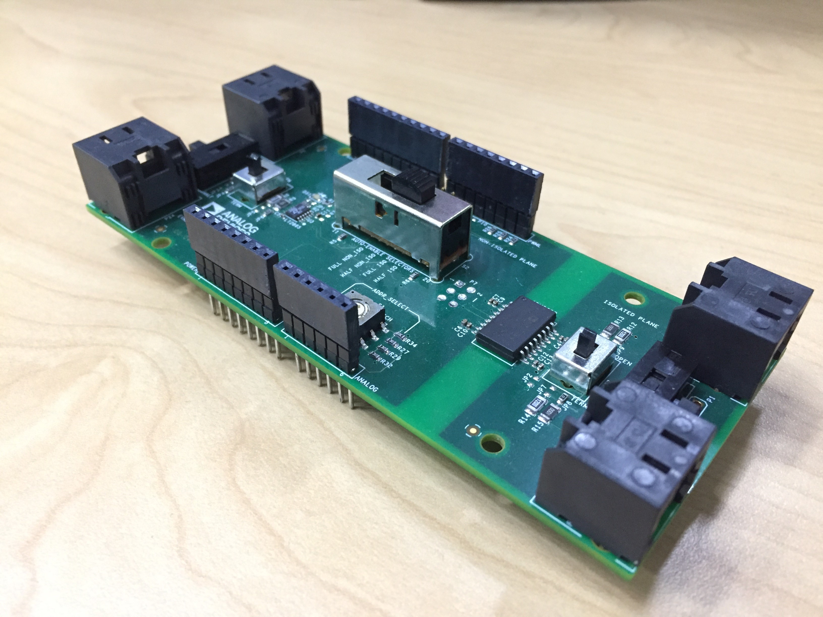
RS-485 Communications
CN0416 can be configured to different settings and operations of the RS-485 communication standard using multiple on-board physical switches. There are three different switches to be configured for both isolated and non-isolated operations as shown below:
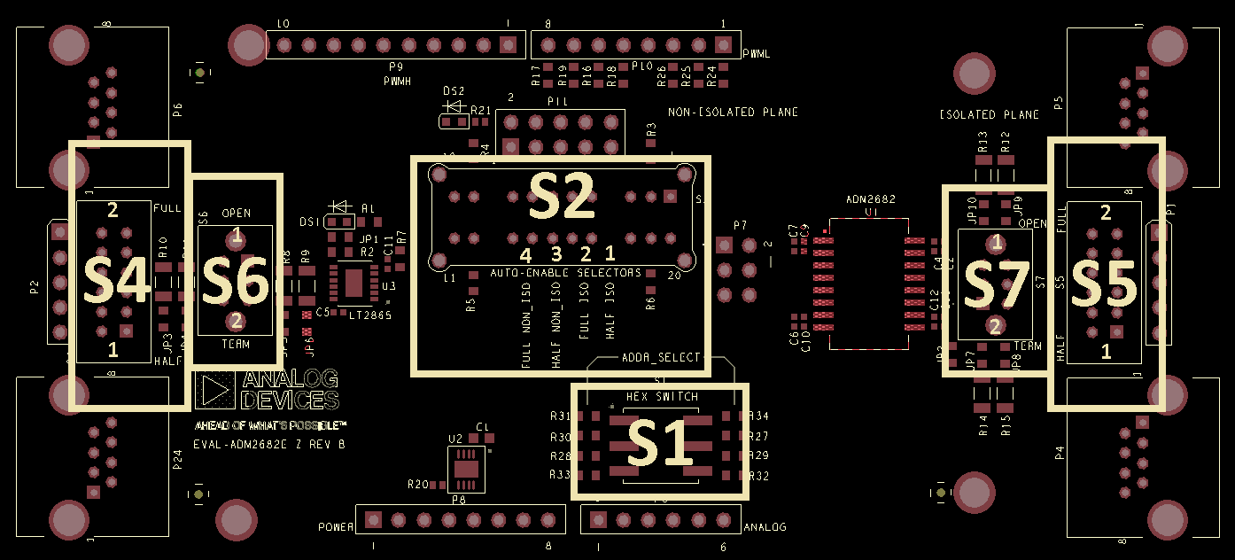
The switches shown in the image above provide the following functions.
Switch |
Function |
|---|---|
S1 |
Configures Address of RS-485 Node |
S2 |
Selects Isolated vs non-Isolated Part and Half/Full Duplex Mode |
S4 |
Selects Physical Layer Half/Full Duplex Mode of non-Isolated LTC2865 |
S5 |
Selects Physical Layer Half/Full Duplex Mode of Isolated ADM2682E |
S6 |
Selects Termination Resistance of non-Isolated LTC2865 |
S7 |
Selects Termination Resistance of Isolated ADM2682E |
Summary of Switch Configurations
In summary, all switch positions for the configurable settings of the CN0416 in RS-485 communications are shown below. (Switch positions that do not matter for a setting are NA)
Isolated, Full Duplex, and Terminated |
2 |
NA |
2 |
NA |
2 |
Isolated, Full Duplex, and Open |
2 |
NA |
2 |
NA |
1 |
Isolated, Half Duplex, and Terminated |
1 |
NA |
1 |
NA |
2 |
Isolated, Half Duplex, and Open |
1 |
NA |
1 |
NA |
1 |
Non-Isolated, Full Duplex, and Terminated |
3 |
2 |
NA |
2 |
NA |
Non-isolated, Full Duplex, and Open |
3 |
2 |
NA |
1 |
NA |
Non-isolated, Half Duplex, and Terminated |
4 |
1 |
NA |
2 |
NA |
Non-isolated, Half Duplex, and Open |
4 |
1 |
NA |
1 |
NA |
Isolated vs Non-Isolated RS-485 Operation
CN0416 can be configured to use either the ADM2682E or the LTC2865 for Half/Full Duplex RS-485 transmission. The difference between the part selected is that the ADM2682E provides complete signal and power isolation, where as the LTC2865 does not isolate the standard RS-485 transmission.
Full Duplex or Half Duplex Operation
CN0416 can be configured to either full-duplex operation or half-duplex operation depending on the application. Switch S4 and S5 controls this setting with the differential RS-485 lines, and switch S2 controls the driver and receiver Enable.
Isolated |
Half-Duplex RS-485 |
S5 = Position 1 (HALF) & S2 = Position 1 (HALF ISO) |
Full-Duplex RS-485 |
S5 = Position 2 (FULL) & S2 = Position 2 (FULL ISO) |
|
Non-Isolated |
Full-Duplex RS-485 |
S4 = Position 2 (FULL) & S2 = Position 3 (FULL NON_ISO) |
Half-Duplex RS-485 |
S4 = Position 1 (HALF) & S2 = Position 4 (HALF NON_ISO) |
Important
When S4 and S5 are in switch position 1, S2 MUST be placed in switch position 1 or 4, depending on the part you are using.
When S4 and S5 are in switch position 2, S2 MUST be placed in switch position 2 or 3, depending on the part you are using.
Cable Length and Termination Selection
The data rate of RS-485 communications varies with the cable length. Below is a figure showing the relationship of data rate and cable length.
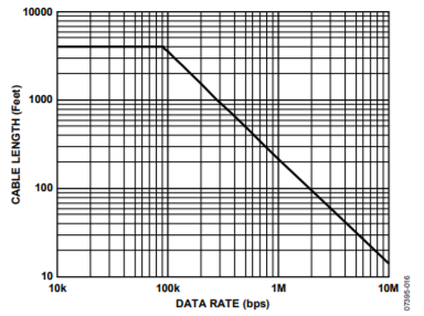
The type of termination also depends on the cable length as well as the cable characteristic impedance. The ordinary CAT5/CAT5E cable has a characteristic impedance of 100 ohms while the RS-485 standard cable has 120 ohms.
By default, the parallel termination resistance is 100 ohms which supports CAT5/CATE cables. But, this can be reconfigured to 120 ohms by disconnecting solder jumpers JP4, JP6, JP8 and, JP10 and shorting solder jumpers JP3, JP5, JP7, JP9.
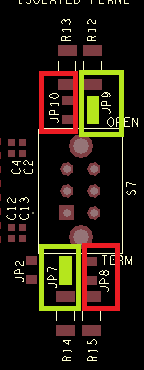
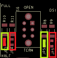
Switch S6 and S7 controls the type of termination of the RS-485 lines.
Isolated |
S7 = Position 1 (OPEN) |
No Line Termination |
S7 = Position 2 (TERM) |
Parallel Resistance Termination |
|
Non-Isolated |
S6 = Position 1 (OPEN) |
No Line Termination |
S6 = Position 2 (TERM) |
Parallel Resistance Termination |
Important
When S6 and S7 are in switch position 1, there is no RS-485 termination. This is suitable for low-power, short transmissions over a total distance less than 0.78 m.
When S6 and S7 are in switch position 2, a parallel resistance termination is inserted. This is suitable for long distance, high power transmissions not exceeding a total distance of 4000 ft.
Hex Switch Addressing
The hex switch can be used to easily setup node addressing when the CN0416 is connected to a microcontroller via the Arduino headers. Bits are connected to analog inputs A0-A3 by default, which can be read as digital inputs by most Arduino platforms. Alternative bit mapping can be selected by resistor-stuff options on the CN0416, shown in parentheses. The bit values of the gpio pins used in node addressing are shown below.
S1 Hex Switch Position |
AIN0 (D7) |
AIN1 (D6) |
AIN2 (D5) |
AIN3 (D4) |
|---|---|---|---|---|
0 |
Low |
Low |
Low |
Low |
1 |
Low |
Low |
Low |
High |
2 |
Low |
Low |
High |
Low |
3 |
Low |
Low |
High |
High |
4 |
Low |
High |
Low |
Low |
5 |
Low |
High |
Low |
High |
6 |
Low |
High |
High |
Low |
7 |
Low |
High |
High |
High |
8 |
High |
Low |
Low |
Low |
9 |
High |
Low |
Low |
High |
A |
High |
Low |
High |
Low |
B |
High |
Low |
High |
High |
C |
High |
High |
Low |
Low |
D |
High |
High |
Low |
High |
E |
High |
High |
High |
Low |
F |
High |
High |
High |
High |
RJ-45 Connection and Wiring Multi-Node Systems
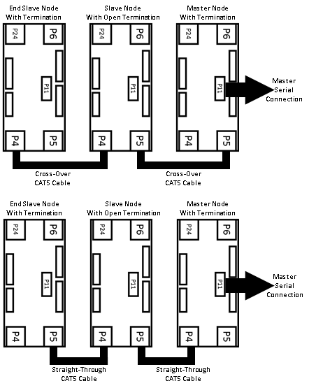
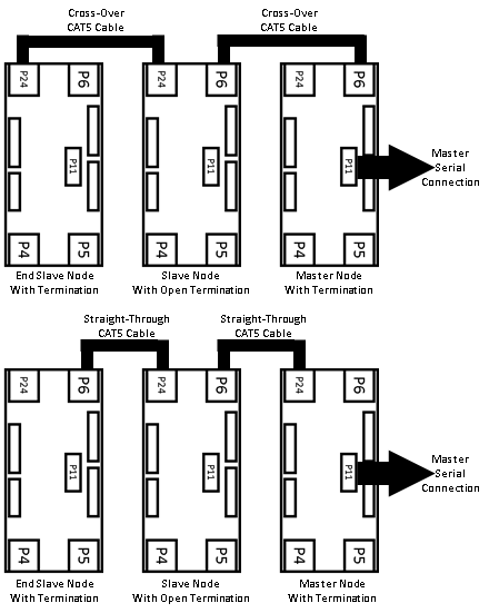
The CN0416 has four RJ-45 ports, P4 and P5 for isolated communications and P6 and P24 for non-isolated communications. Each pair has a cross-over connection with each other. This facilitates the use of either a straight-through or crossover CAT5 cable.
Important
With a straight-through connection, the CAT5 cable should connect two boards using the same port, e.g. (P4 of a master node is connected to P4 of a slave node in isolated communications).
Important
With a crossover connection, the CAT5 cable should connect two boards using opposite ports, e.g. (P6 of a master node is connected to P24 of a slave node in non-isolated communications).
Below shows illustrations of connecting multiple nodes using either a straight-through or a crossover cable for both isolated and non-isolated communications.
For Isolated Communications:
For Non-Isolated Communications:
ADALM-UARTJTAG Connection
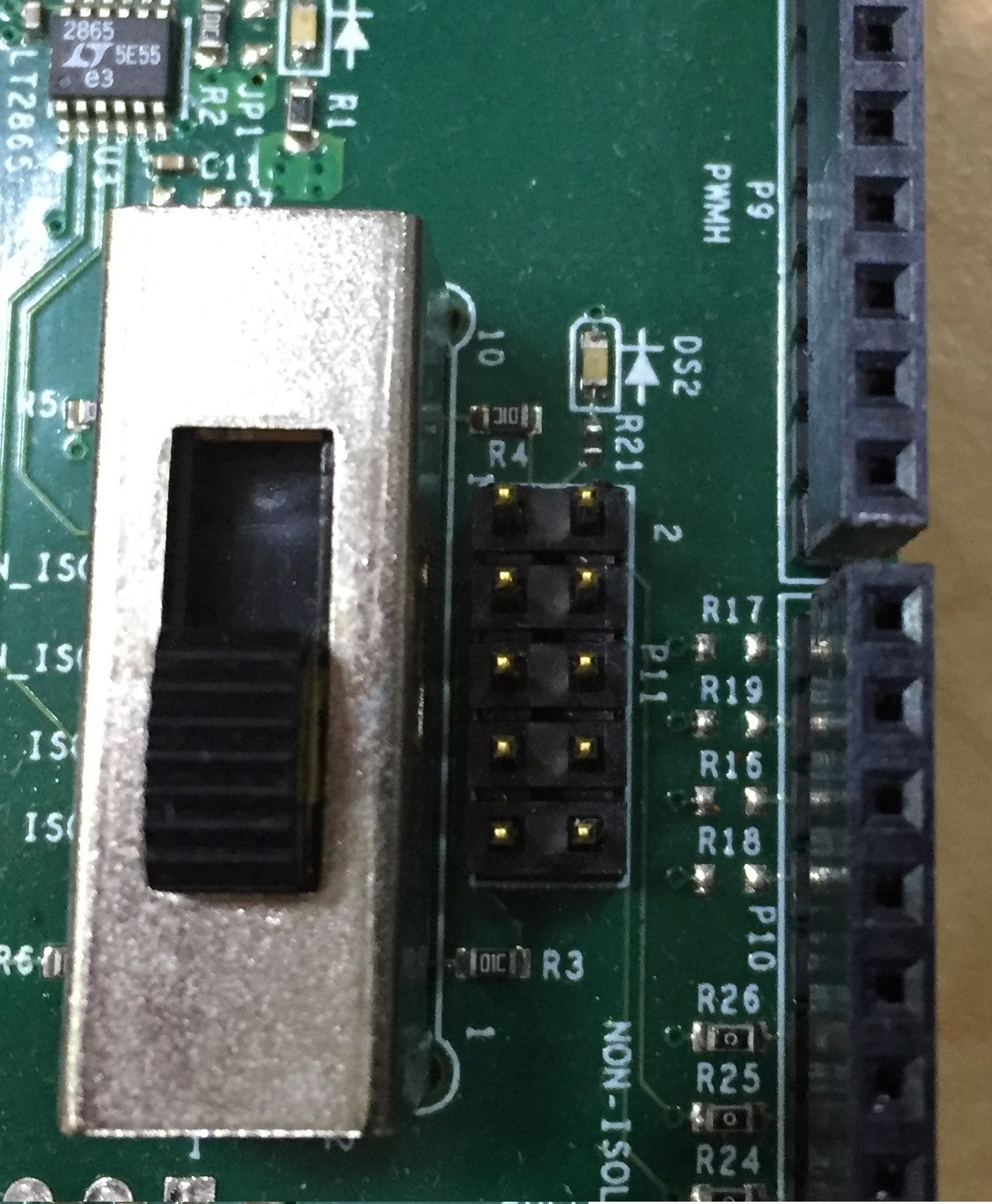
The CN0416 has a 10 pin 5x2 connector to interface with an ADALM-UARTJTAG. The yellow LED DS2 will indicate a live connection between the two devices.
Important
For half duplex set-ups, the ADALM-UARTJTAG needs to be setup for RS485 communications.
Schematic, PCB Layout, Bill of Materials
Download
EVAL-CN0416-ARDZ Design & Integration Files
Schematics
PCB Layout
Bill of Materials
Allegro Project
Registration
Tip
Receive software update notifications, documentation updates, view the latest videos, and more when you register your hardware. Register to receive all these great benefits and more!
End of Document