EVAL-LTPA-LNAKIT

LTpowerAnalyzer™ Low Noise Amplifier Kit

Overview

The EVAL-LTPA-LNAKIT is an add-on hardware kit featuring a USB-powered low noise amplifier (LNA) module designed for the LTpowerAnalyzer™ system. This external LNA module can be used to amplify the low-level AC component of a power supply’s output voltage, allowing the LTpowerAnalyzer™ to perform high-resolution noise measurements and generate detailed noise density plots.

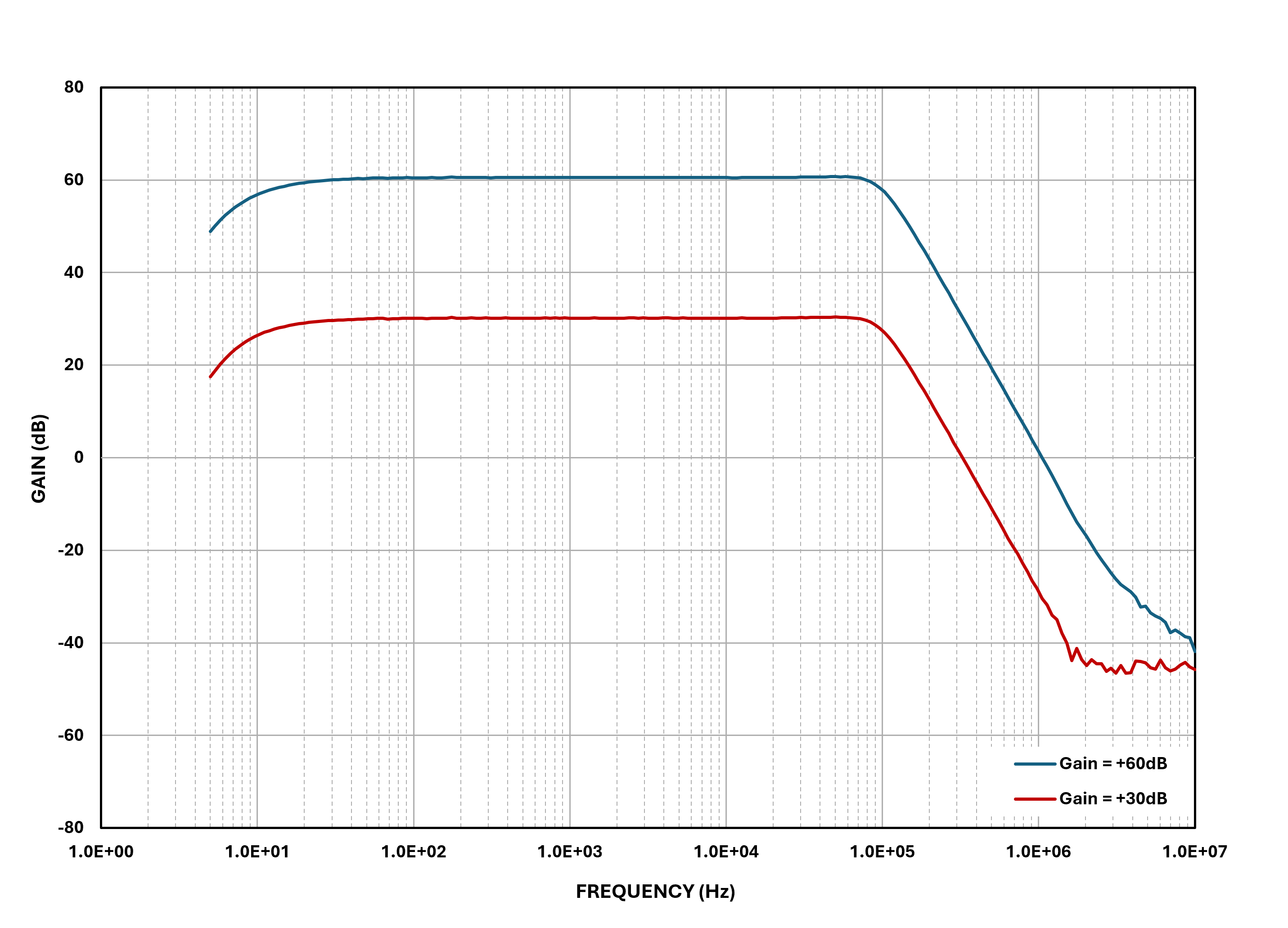
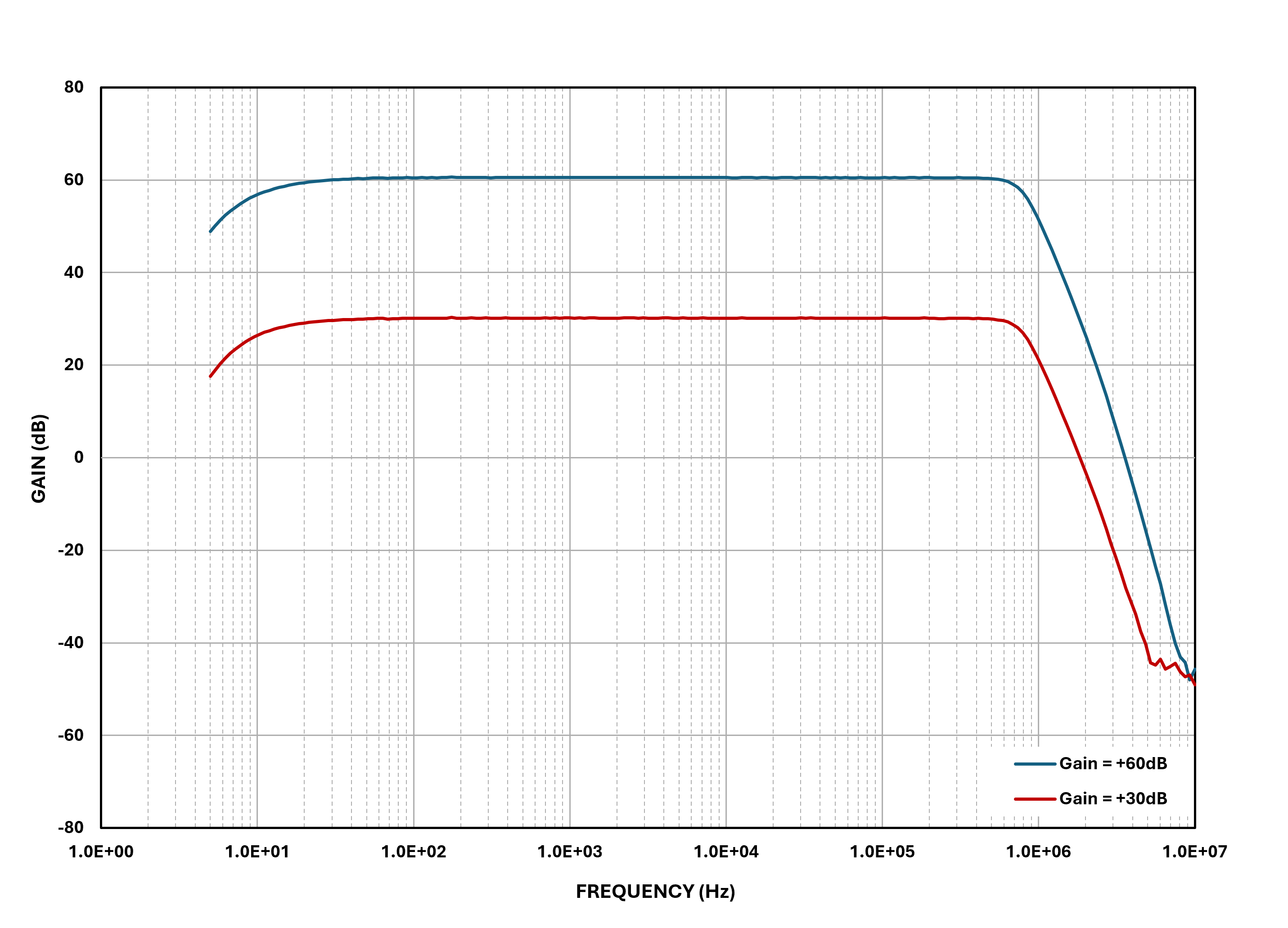
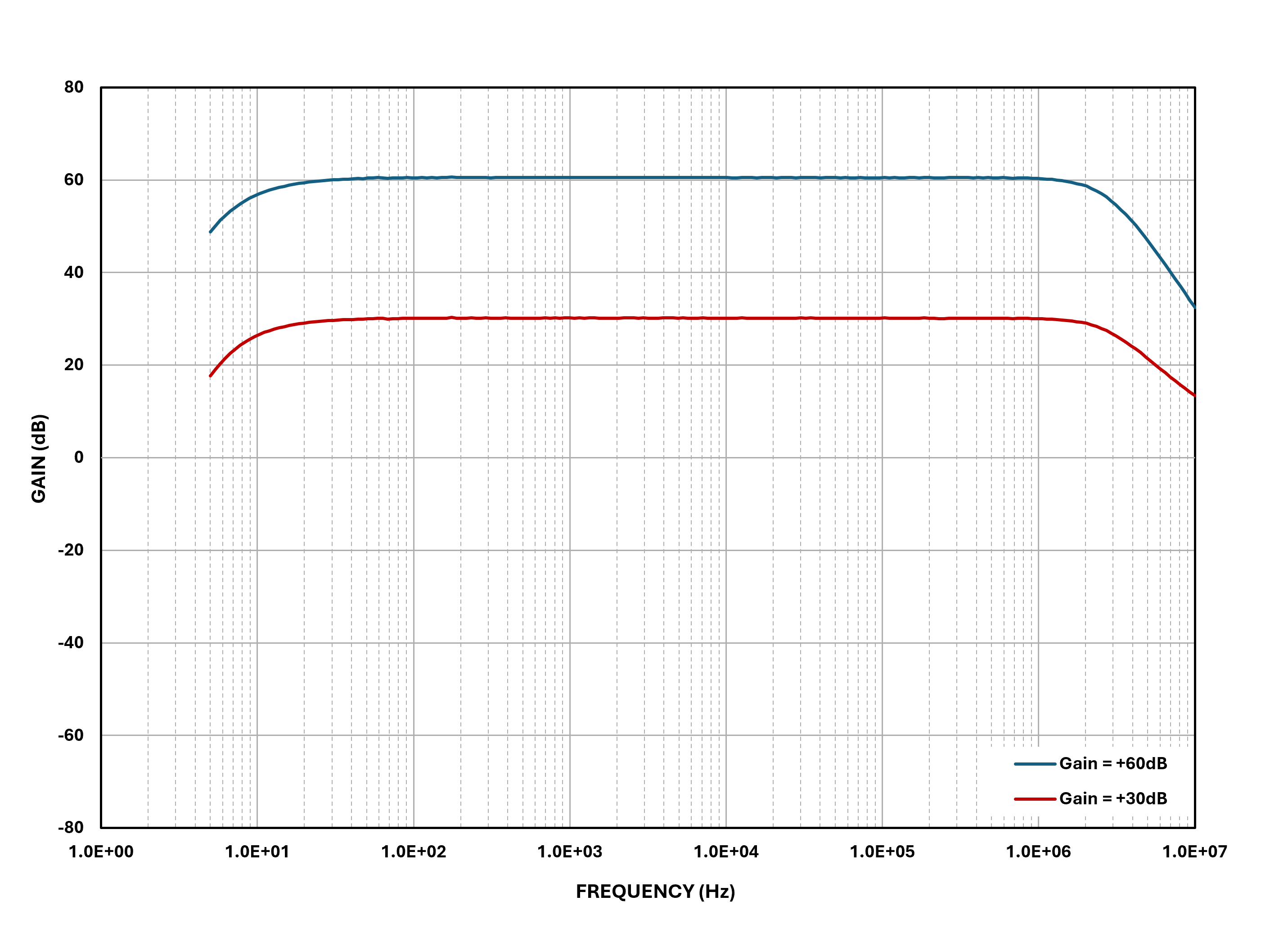
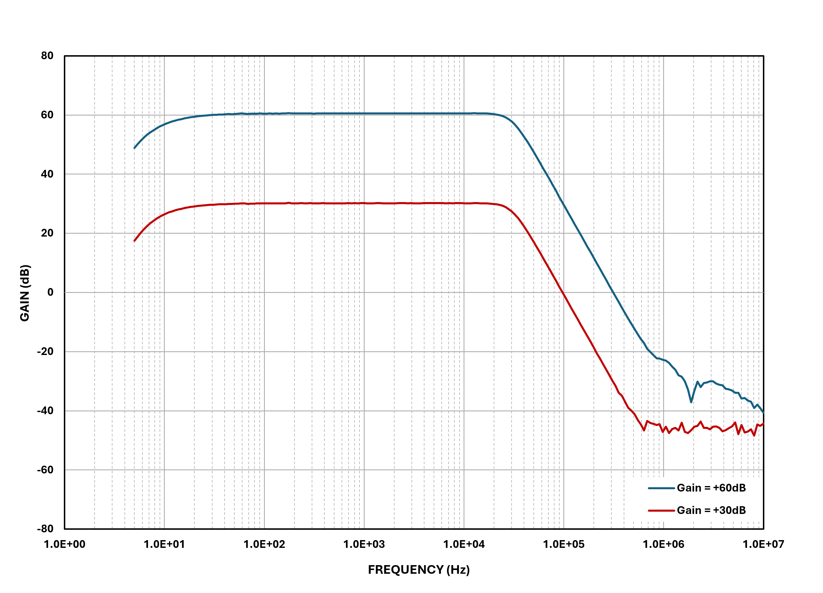
The LNA module has software-programmable gain (+30 dB, +60 dB) and bandwidth (30 kHz, 100 kHz, 1 MHz, 10 MHz) settings, allowing the user to easily adjust the amplifier response based on the performance of their DUT.
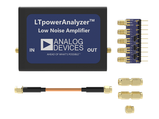
https://media.githubusercontent.com/media/analogdevicesinc/system-level/main/docs/solutions/reference-designs/eval-ltpa-lnakit/EVAL-LTPA-LNAKIT_top-evaluation-board.png

Figure 1 EVAL-LTPA-LNAKIT

The EVAL-LTPA-LNAKIT includes the following boards and accessories:

  • 1 pc. LNA Module

  • 1 pc. SMA Interface Board

  • 1 pc. 6” SMA to SMA Cable

  • 1 pc. SMA Shorting Cap

  • 2 pcs. Male-to-Male SMA Adapter

Features

  • Gain: +30 dB or +60 dB

  • Bandwidth: 30 kHz, 100 kHz, 1 MHz, or 10 MHz

  • Max Output Power: +17 dBm

  • Input and Output Impedance: 50 Ohms

  • USB-powered device

  • Compact form-factor for portable applications, similar to the main LTpowerAnalyzer™ kit.

Applications

  • Power Supply Noise Measurement and Noise Density Plots

Typical Gain Profiles
https://media.githubusercontent.com/media/analogdevicesinc/system-level/main/docs/solutions/reference-designs/eval-ltpa-lnakit/EVAL-LTPA-LNAKIT_30khz-gain-profile.png

Figure 2 LNA Gain Profile @ 30 kHz Setting

https://media.githubusercontent.com/media/analogdevicesinc/system-level/main/docs/solutions/reference-designs/eval-ltpa-lnakit/EVAL-LTPA-LNAKIT_100khz-gain-profile.png

Figure 3 LNA Gain Profile @ 100 kHz Setting

https://media.githubusercontent.com/media/analogdevicesinc/system-level/main/docs/solutions/reference-designs/eval-ltpa-lnakit/EVAL-LTPA-LNAKIT_1mhz-gain-profile.png

Figure 4 LNA Gain Profile @ 1 MHz Setting

https://media.githubusercontent.com/media/analogdevicesinc/system-level/main/docs/solutions/reference-designs/eval-ltpa-lnakit/EVAL-LTPA-LNAKIT_10mhz-gain-profile.png

Figure 5 LNA Gain Profile @ 10 MHz Setting

Typical Application

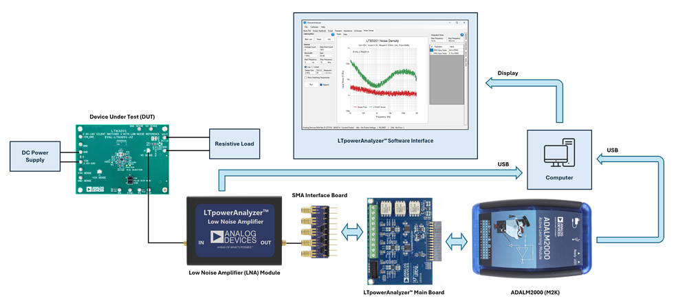
Figure 8 illustrates the basic hardware setup for performing noise measurements using the LTpowerAnalyzer™.
https://media.githubusercontent.com/media/analogdevicesinc/system-level/main/docs/solutions/reference-designs/eval-ltpa-lnakit/EVAL-LTPA-LNAKIT_hw-setup-noise.png

Figure 6 LTpowerAnalyzer™ Noise Measurement Setup

Step by Step Procedure

  1. Connect the M2K to the 40-pin socket on the main board.

  2. Connect the SMA interface board to the screw terminal block on the main board.

  3. On the SMA interface board, place the J2 jumper in the ‘G’ position.

  4. Connect the IN port of the LNA module to the output of the DUT.

  5. Connect the OUT port of the LNA module to the IN+/IN- port on the SMA interface board using either an SMA cable, or a male-to-male SMA adapter.

  6. Using the USB cables, connect the ADALM2000 and the LNA to a computer.

  7. With the power off, connect the DC power supply to the input terminals of the DUT.

  8. With the power off, connect the load to the output terminals of the DUT.

  9. Configure the settings of the DC power supply as needed and enable the output.

Important

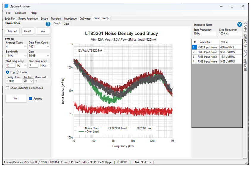
The type of load used in the setup can negatively affect the noise measurements. Below is an example plot showing the difference with using a 4 Ohm resistive load, a Keysight E34243A electronic load, and the RL2000 efficiency meter current load.

For the best results, it is recommended to always use a resistive load.
https://media.githubusercontent.com/media/analogdevicesinc/system-level/main/docs/solutions/reference-designs/eval-ltpa-lnakit/EVAL-LTPA-LNAKIT_noise-measurement-sw-loading.png

Figure 7 Load Effects on Noise Measurements

  1. Run the LTpowerAnalyzer™ software and click on the Noise Sweep tab.

  2. Configure the noise sweep parameters based on the test requirements for the DUT.

  3. Click on the Run button to initiate the measurement sweep.

  4. Click on the Analysis tab to view the integrated noise value. Adjust the start and stop freqeuncies as required.

Note

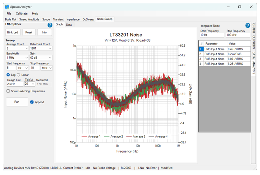
The Noise Sweep can be run with 1, 2, 4, or 8 averages. Increasing the number of averages will slow down the sweep, but will also reduce variation.
https://media.githubusercontent.com/media/analogdevicesinc/system-level/main/docs/solutions/reference-designs/eval-ltpa-lnakit/EVAL-LTPA-LNAKIT_noise-measurement-sw-averaging.png

Figure 8 Noise Sweep Averaging

Tip

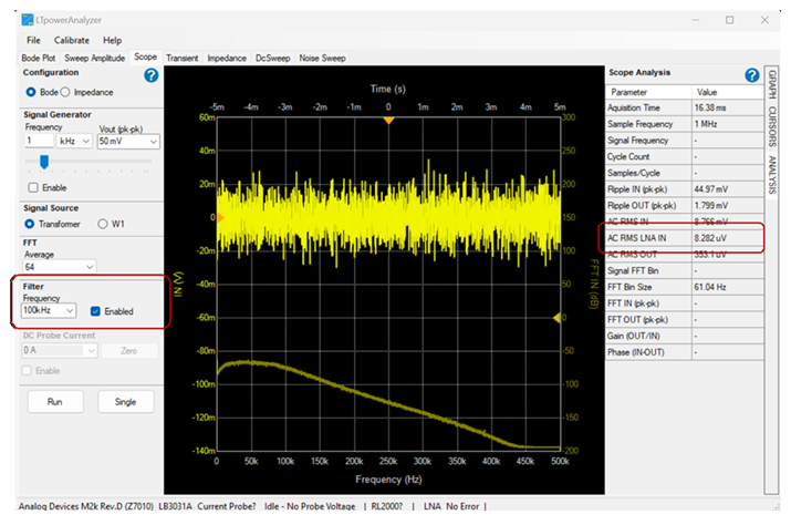
The LTpowerAnalyzer™ Scope can be used to validate the integrated noise value. After setting up the LNA gain and filter, open the Scope tab, set the Filter Frequency, enable the filter, and click on the Run button. The noise value will be displayed in the Analysis tab as AC RMS LNA IN, which then can be compared to the integrated noise measurement in the Noise Sweep tab.
https://media.githubusercontent.com/media/analogdevicesinc/system-level/main/docs/solutions/reference-designs/eval-ltpa-lnakit/EVAL-LTPA-LNAKIT_noise-measurement-sw-scope.png

Figure 9 Scope Analysis of AC RMS Noise

Important

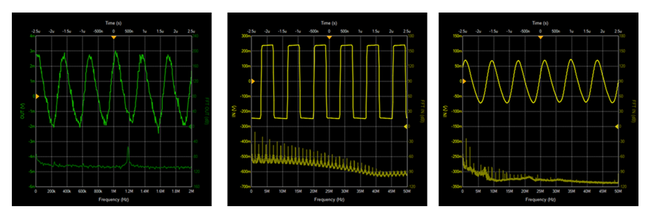
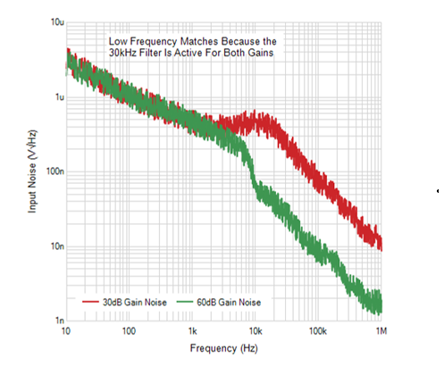
When selecting the LNA gain setting, it is important to note that the IN port of the LTpowerAnalyzer™ main board has a maximum input level of +/- 230 mV. If the output ripple of a switching power supply is relatively high, the amplified output of the LNA may exceed the limits of the main board, leading to bogus noise measurements.

Before starting any noise measurements, always check using the Scope tab if the IN signal is clipping and lower the gain to +30 dB if needed.
https://media.githubusercontent.com/media/analogdevicesinc/system-level/main/docs/solutions/reference-designs/eval-ltpa-lnakit/EVAL-LTPA-LNAKIT_gain-selection-scope-clipping-example.png

Figure 10 Checking for IN Clipping Using the Scope Tab

https://media.githubusercontent.com/media/analogdevicesinc/system-level/main/docs/solutions/reference-designs/eval-ltpa-lnakit/EVAL-LTPA-LNAKIT_gain-selection-noise-example.png

Figure 11 Noise Measurement Example with IN Clipping @ +60 dB Gain Setting

Noise Sweep Interface Reference

Measurement Setup

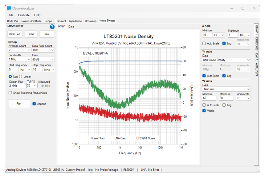
The Noise Sweep Measurement Setup is on the left side of the window.
https://media.githubusercontent.com/media/analogdevicesinc/system-level/main/docs/solutions/reference-designs/eval-ltpa-lnakit/EVAL-LTPA-LNAKIT_noise-measurement-sw-setup.png

Figure 12 Noise Sweep Setup

Table 1 LNAmplifier Controls

Button

Description

Blink LED

Blinks the board LED.

Reset

Returns all settings to their default values.

Info

Displays information about the LNA (e.g., hardware and firmware versions, serial number, serial port, etc.).

Table 2 Sweep Settings

Setting

Description

Average Count

Sets the number of FFT averages per sweep.

Data Point Count

Sets the number of data points per sweep.

Bandwidth

Sets the bandwidth of the LNA (30 kHz, 100 kHz, 1 MHz or 10 MHz).

Gain

Sets the LNA gain (+30 dB or +60 dB).

Start Frequency

Sets the starting frequency value in the sweep.

Stop Frequency

Sets the final frequency value in the sweep.

Log / Linear

Sets the frequency scaling of the sweep.

Design Fsw

Specifies the expected switching frequency of the DUT.

Tol (%)

Sets the error tolerance of the switching frequency measurement.

Measured

Displays the switching frequency measurement.

Show Switcher Frequencies

Check this box to show the first 4 switching harmonics in the sweep plot.

Run / Stop

Initiates a noise sweep. A sweep in progress can be stopped by clicking on this button again.

Append

Check this box to overlay succeeding sweep plots on top of the currently displayed data. When left unchecked, all previous graphs and data will be erased at the start of the next sweep.

Table 3 Plot Settings: X-Axis

Setting

Description

Minimum

Sets the minimum value displayed on the X-Axis.

Maximum

Sets the maximum value displayed on the X-Axis.

Increments

Specifies the number of increments for linear scaling.

AutoScale

Check this box to automatically scale the X-Axis.

Log

Toggles between logarithmic and linear scaling.

Table 4 Plot Settings: Y1/Y2-Axis

Setting

Description

Data

Selects the data to display.

Minimum

Sets the minimum value displayed on the Y1/Y2-Axis.

Maximum

Sets the maximum value displayed on the Y1/Y2-Axis.

Increments

Specifies the number of increments for linear scaling.

AutoScale

Check this box to automatically scale the Y1/Y2-Axis.

Log

Toggles between logarithmic and linear scaling.

Visible (Y2-Axis)

Toggles visibility for the Y2 axis.

Measurement Analysis

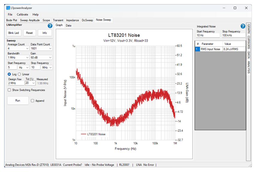
The Noise Sweep Measurement Analysis is on the right side of the window. The RMS integrated noise between the Start Frequency and Stop Frequency is calculated and displayed for each sweep.
https://media.githubusercontent.com/media/analogdevicesinc/system-level/main/docs/solutions/reference-designs/eval-ltpa-lnakit/EVAL-LTPA-LNAKIT_noise-measurement-sw-analysis.png

Figure 13 Noise Sweep Analysis

Table 5 Noise Integration Settings

Setting

Description

Start Frequency

Sets the lowest frequency for integration.

Stop Frequency

Sets the highest frequency for integration.

Help and Support

For questions and more information, please visit the Analog Devices EngineerZone Support Community.