Accelerometer Demo using Wi-Fi (with EVAL-ADXL362-ARDZ)
The ADuCM3029_demo_esp8266 is a Wi-Fi demo project for the EVAL-ADICUP3029 base board with additional EVAL-ADXL362-ARDZ shield, created using the Analog Devices Cross Core Embedded Studio.
Important
This documentation is to be used with the source code hosted on Github. The link is available in the Obtaining the Source Code section.
General Description/Overview
The ADuCM3029_demo_esp8266 project uses the EVAL-ADXL362-ARDZ shield which has an ADXL362 3-axis MEMS accelerometer and a incorporated NHD-C12832A1Z-NSW-BBW display (128x32). However, for this example the display is not used.
The EVAL-ADICUP3029 is designed for IOT (Internet of Things) applications in mind, and therefore comes with on board Wi-Fi ESP8266 module.
Also, in order to fully make use of the IOT capability, MQTT messaging protocol is used as it is extremely simple and lightweight.
Demo Requirements
The following is a list of items needed in order to replicate this demo.
Hardware
EVAL-ADICUP3029
EVAL-ADXL362-ARDZ
Mirco USB to USB cable
PC or Laptop with a USB port
Software
ADuCM3029_demo_adxl362 software
CrossCore Embedded Studio (2.6.0 or higher)
ADuCM302x DFP (2.0.0 or higher)
ADICUP3029 BSP (1.1.0 or higher)
Mosquitto Broker
Setting up the Hardware
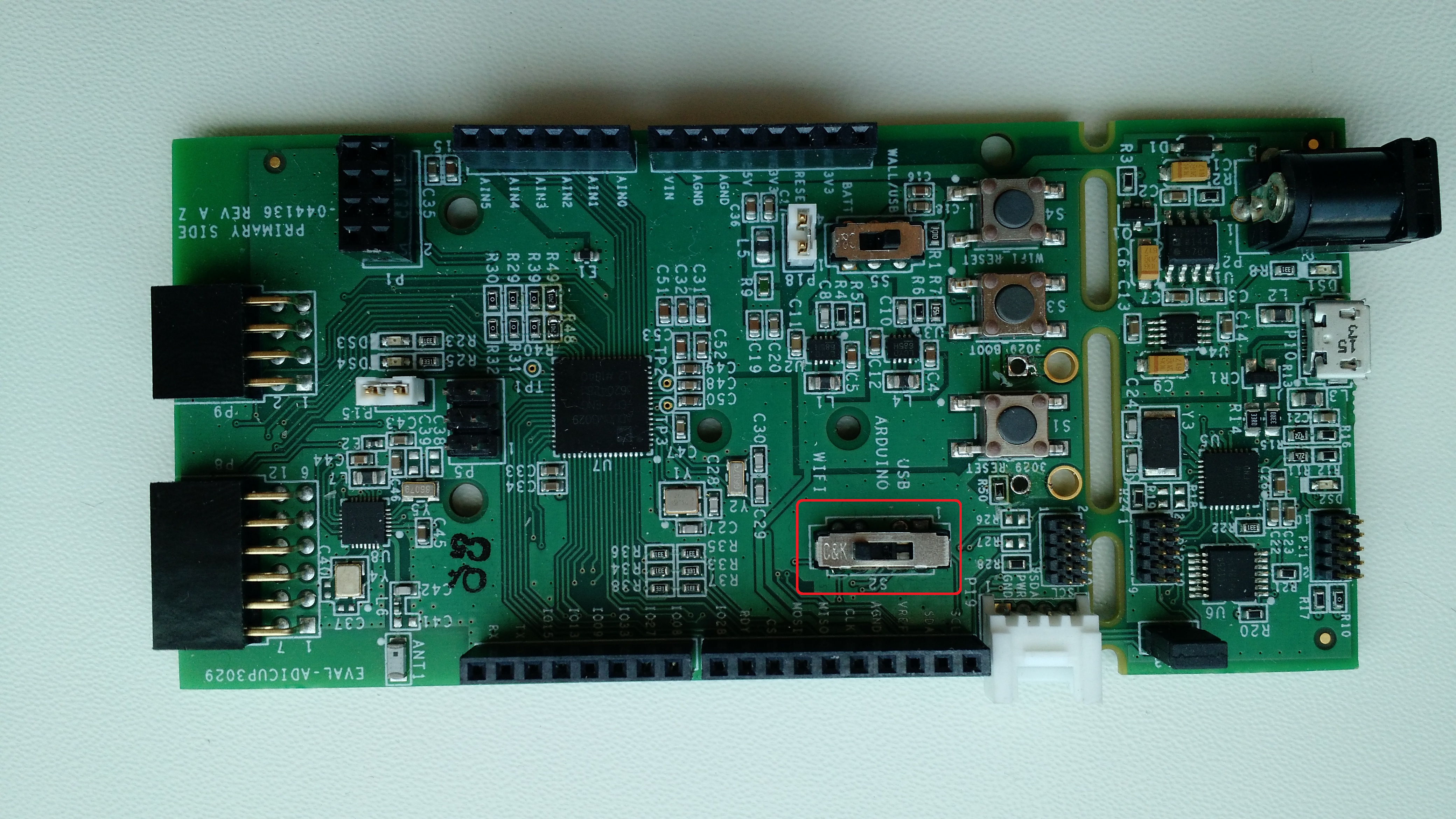
Move the S2 switch to the WiFi position on the EVAL-ADICUP3029.
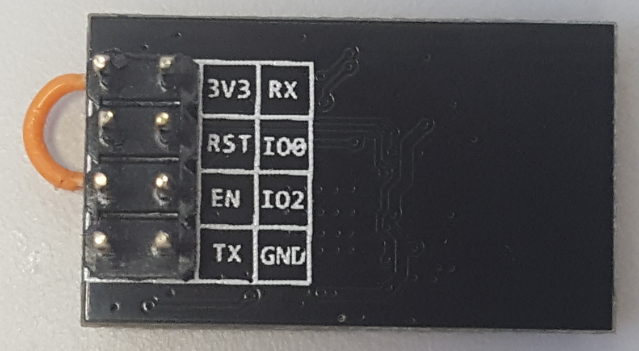
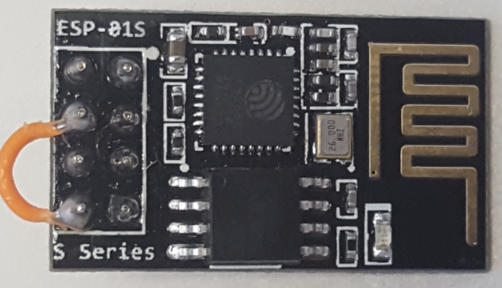
The ESP8266 Enable Pin needs to be tied directly to 3.3V or pulled high to the GPIO via a 10K ohm resistor. Because this is not currently on the Rev B or Rev C version of the ADICUP3029, you will need to solder a small fly wire from the 3.3V pin to the enable pin.
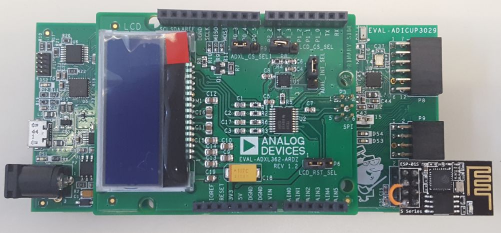
 * Plug the ESP8266 in the P1 connector on the EVAL-ADICUP3029.
Plug the EVAL-ADXL362-ARDZ shield in the EVAL-ADICUP3029 base board.
Plug the USB cable
Obtaining the Software
There are two basic ways to program the ADICUP3029 with the software for the ESP8266.
Dragging and Dropping the .Hex to the Daplink drive
Building, Compiling, and Debugging using CCES
Using the drag and drop method, the software is going to be a version that Analog Devices creates for testing and evaluation purposes. This is the EASIEST way to get started with the reference design
Importing the project into CrossCore is going to allow you to change parameters and customize the software to fit your needs, but will be a bit more advanced and will require you to download the CrossCore toolchain.
The software for the ADuCM3029_demo_esp8266 can be found here:
Download
Prebuilt ESP8266 Hex File
Complete ESP8266 Source Files
Note
For more information on importing, debugging, or other tools related questions, please see the tools user guide.
Configuring the Software (parameters.h)
** Accelerometer scan interval** - how often to update sensor information. Set the // SCAN_SENSOR_TIME // parameter (ADXL362.h):
#define SCAN_SENSOR_TIME 500 // msecs
** Sensor activity and inactivity thresholds** - ACCEL_CFG_ACT_TRESH and ACCEL_CFG_INACT_TRESH paramaters used to determine at which acceleration values the sensor can react at sleep/wake-up commands:
#define ACCEL_CFG_ACT_TRESH    50      // msecs
#define ACCEL_CFG_INACT_TRESH  50      // msecs
** Sensor activity and inactivity time** - ACCEL_CFG_ACT_TIMER and ACCEL_CFG_INACT_TIMER paramaters used to determine sleep/wake-up intervals:
#define ACCEL_CFG_ACT_TIMER   100      // msecs
#define ACCEL_CFG_INACT_TIMER 10       // msecs
Network parameters Here you should set your Wi-Fi connection and MQTT information:
#define WIFI_SSID       "***"
#define WIFI_PASS       "***"
#define SERVER_ADDR     "***"
Using an MQTT Broker
The program connects to a WiFi network and to a TCP MQTT broker. After receiving the SUBACK confirmation from the server, the program enters an infinite loop where it waits for an ADXL-362 interrupt which is triggered when the acceleration on any axes is greater than 50 mG. Afterwards, the program publishes the x, y, z readings on adxl topic. A subscriber to this topic can view this information.
Installing the Mosquitto Broker
This example uses the Eclipse Mosquitto which is an open source (EPL/EDL licensed) message broker that implements the MQTT protocol versions 3.1 and 3.1.1. However, the user is free to use his favorite MQTT broker with minimal changes. MQTT provides a lightweight method of carrying out messaging using a publish/subscribe model. This makes it suitable for “Internet of Things” messaging such as with low power sensors or mobile devices such as phones, embedded computers or microcontrollers.
Hint
Alternatively, there is an additional step-by-step procedure written which can be used in combination with the steps outlined below. The combination of both procedures should be enough to get most PC/laptops working.Installing and Configuring Mosquitto
Double click the downloaded .exe file, and install the Mosquitto program
During the install, Mosquitto will ask you to make sure you have 2 other programs installed.
Click the links within the Windows install wizard BEFORE completing the Mosquitto install.
-
Refer to pictures outlined in the additional step by step instructions.
-
Make sure these additional programs are installed before you continue
Click next and finish the installation.
You may run into an issue that says “VCRUNTIME140.dll is missing. In order to proceed you must first have this installed.
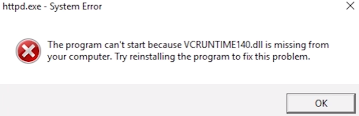
After looking around, I found a great website to download the DLL files from, as well as a great video that shows you have to fix the issue, and it did work for me. Please note, that this solution is **NOT* affiliated with Analog Devices, and Analog Devices assumes no responsibility for any problems or damages occurred during this process.*
Re-Run the Mosquitto.exe file, inorder to complete the installation process.
Setting up Mosquitto to Receive MQTT Data
With Mosquitto and other software properly installed, you should be able to run mosquitto. Open a Command Prompt and navigate to the folder where mosquitto is installed. The default location is C:\Program Files (x86)\mosquitto
Type mosquitto.exe -v to start the broker in verbose mode. Copy this code block into your command line editor to navigate to the folder and execute the program:<code> cd C:\Program Files (x86)\mosquitto\mosquitto.exe -v </code> It should look like the following picture

Important
Make sure that your computer or laptop is connected to the same network you are going to configure in the parameters.h file. Once you run the executable, Mosquitto assumes that you are running on that network.
The mosquitto broker is now running locally and has the same IP as your machine and by default runs on port 1883. Open a new Command Prompt and type ipconfig to get your local IP address
In the parameters.h header file you need to configure the following parameters:
SSID = ""         *Service set identifier, name of the WiFi network to connect the ESP8266*
PASS = ""         *WiFi network password*
SERVER_ADDR = ""  *IP of the mosquitto broker from the previous step*
SERVER_PORT = "1883"     //by default is 1883//
Open a third Command Prompt and navigate to the folder where mosquitto is installed and type this command and hit the <ENTER> key:<code> cd C:\Program Files (x86)\mosquitto\mosquitto_sub -t adxl </code> This command subscribes to the topic and will display the accelerometer data. It should look similar to the image below.

Outputting Data
You are now ready to flash the program on the ADICUP3029 and run it. Before downloading the code, please press the WIFI_RESET button (S4) on the ADICUP3029.
If everything works fine, in the CrossCore Embedded Studio console you should see:
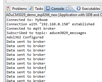
The program has connected to the local WiFi network, to the TCP mosquitto broker, subscribed to subtopic an received SUBACK as a confirmation from the broker.
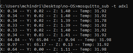
The program will publish x, y, z data on the adxl topic. In order to view this information, we can use mosquitto_sub and subscribe to the adxl topic.
At each ADXL362 movement, an interrupt is triggered and as a result, the x, y, z information is published. In the console publishing sensor reading message is displayed, while in the mosquitto_sub cmd window you should see the values of x, y, z axis:
How to use the Tools
The official tool we promote for use with the EVAL-ADICUP3029 is CrossCore Embedded Studio. For more information on downloading the tools and a quick start guide on how to use the tool basics, please check out the Tools Overview page.
Importing
For more detailed instructions on importing this application/demo example into the CrossCore Embedded Studio tools, please view our How to import existing projects into your workspace section.
Debugging
For more detailed instructions on importing this application/demo example into the CrossCore Embedded Studio tools, please view our How to configure the debug session section.
Project Structure
The ADuCM3029_demo_esp8266 project use basic ARM Cortex-M C/C++ Project
structure. This project contains: system initialization part - disabling
watchdog, setting system clock, enabling clock for peripheral; port
configuration for SPI, accelerometer sensor; ESP8266 initialization - UART and
GPIO.
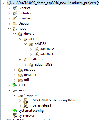
In the srcs/app_src folder you will find the source file for the main application:
ADuCM3029_demo_esp8266.c: is the file containing the main function
parameters.h: is the files where configurable parameters can be modified
noos: is directory containing linked resources from the noos repo. Eg. Adxl362 driver, network files and platform drivers (spi, uart)
Mqtt client is linked as static library. Can be found in noos/libraries/mqtt
To build mqtt library run the following command in the ADuCM3029_demo_esp8266 folder:
make libs
End of Document