Layout Considerations
The ADL5324 has several passive components surrounding the IC which directly influence the tuning frequency of the device. The location of these capacitors is critical to the accurate determination of the tuning frequency.
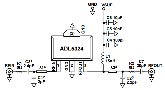
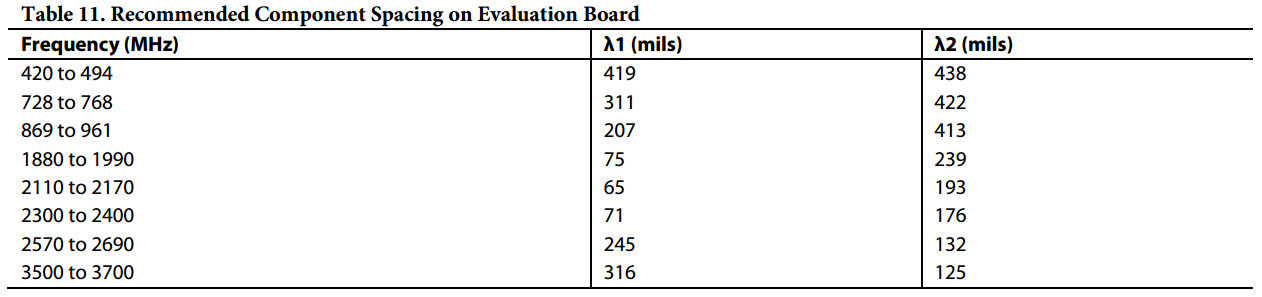
The component spacing for tuning capacitors C1 and C2 is detailed in the ADL5324 datasheet over a variety of frequencies. A table from the datasheet, detailing this information, is listed below.
Placement of the AC coupling capacitors, power supply bypassing capacitors and DC bias inductor should follow the recommendation of the datasheet, but are slightly less critical than the tuning capacitors.