EVAL-CN0391-ARDZ Shield
Overview
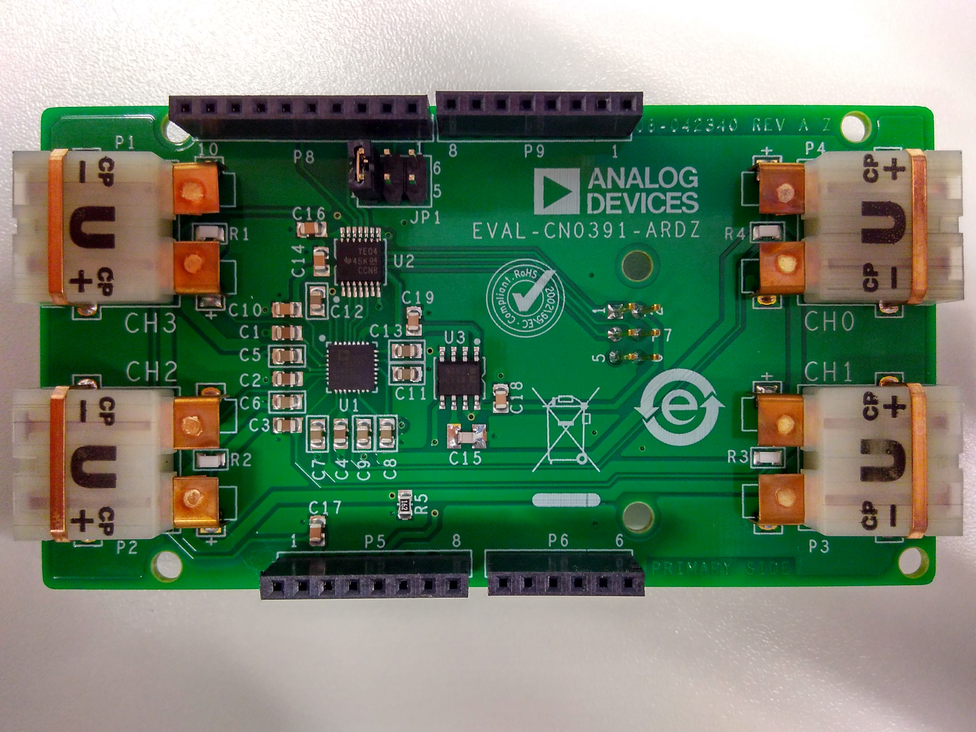
The EVAL-CN0391-ARDZ shield is a single supply, multi channel thermocouple temperature meter. The CN0391 uses ad7124-8 8-Channel, Low Noise, Low Power, 24-Bit, Sigma-Delta ADC with PGA and Reference as integrated solution for multi channel thermocouple temperature measurement with RTD cold junction compensation.
Equipment Needed
EVAL-CN0391-ARDZ Circuit Evaluation Board
EVAL-ADICUP360 Development Board or compatible Arduino platform Board.
Any combination of B, E, J, K, N, R, S, T type thermocouples (total of 4)
PC with Microsoft Windows 7 64-bit or later and USB 2.0 port or higher
Serial terminal software
Such as Putty or Tera Term
General Setup
Connect the EVAL-CN0391-ARDZ to EVAL-ADICUP360 board
Connect 4 thermocouples to EVAL-CN0391-ARDZ P1~P4, marked on PCB with CH0~CH3
Connect the EVAL-ADICUP360 USER USB port to PC with USB cable
Connectors and Jumper Configurations
Thermocouple Connectors
Each of the four(4) channels uses an Omega style connector for the thermocouples, which makes it easier to plug in and out different thermocouple types. Type U was selected so that all the channels on the board (P1 - P4) would be universal and interchangeable.
There is an RTD beneath the copper tabs of each connector which is used to measure the cold junction temperature. So no external cold junction measurement is needed with this board.
Chip Select
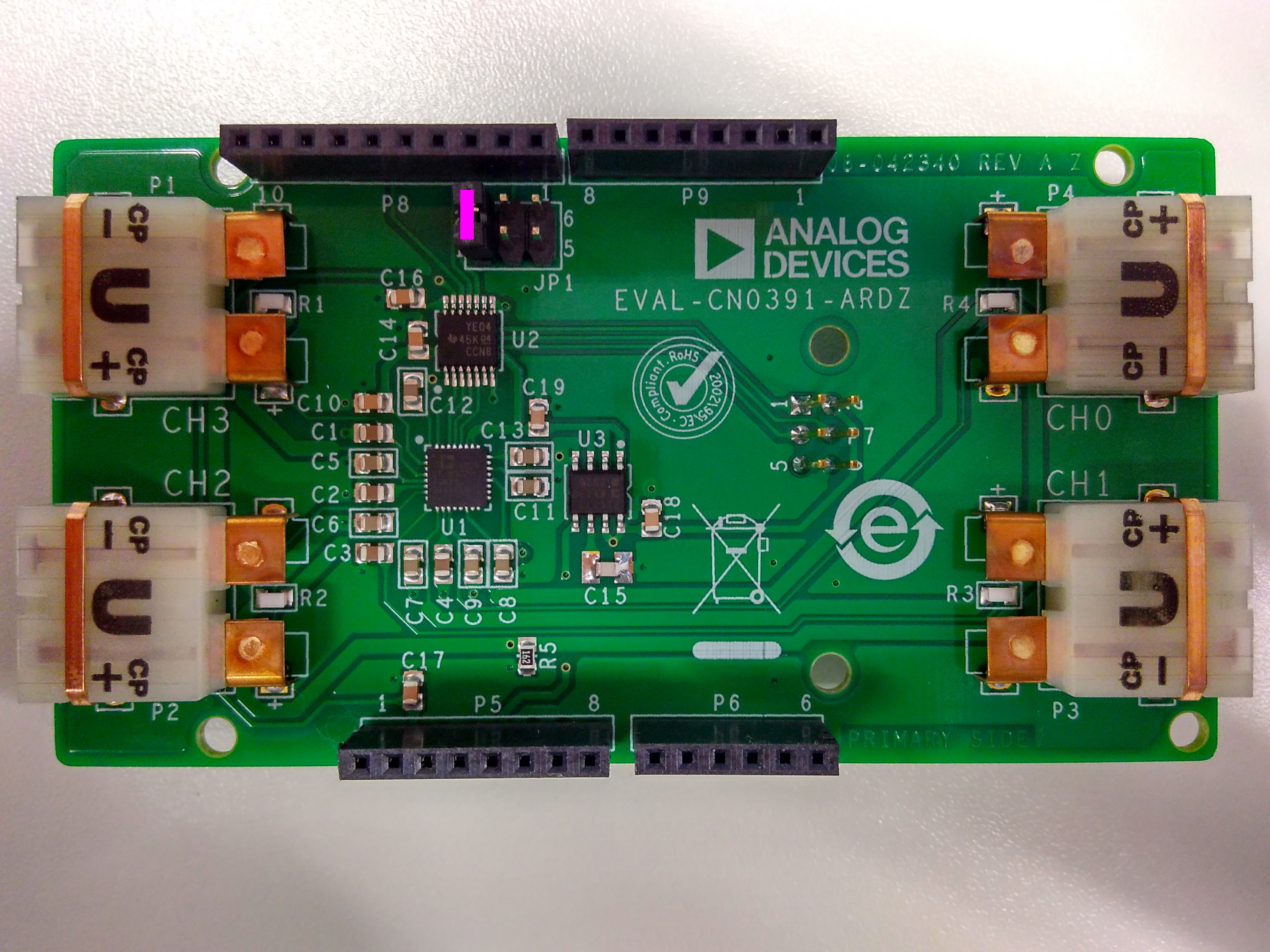
The chip select header (JP1) is used to select the chip select pin on the AD7124. This allows for flexibility on the SPI bus when stacking multiple Arduino shields together. To change the chip select of the AD7124, all you need to do is move the shunt to one of the below locations, and then make the corresponding change in software.
Jumper Position (JP1) |
AD7124 Chip Select Pin (P8) |
|---|---|
Across Pin 1 and 2 |
Pin 3 |
Across Pin 3 and 4 |
Pin 2 |
Across Pin 5 and 6 |
Pin 1 |
To use the EVAL-CN0391-ARDZ with the software we provide, please connect the thermocouples to each channel and set the software to corresponding thermocouple type/channel . Please set the default jumper position as pictured:
Digital Communications
The AD7124 Analog to Digital converter, measures each sensor input channel on the board. The results are then sent over to the processor via the SPI communications protocol. More reading about SPI Communications can be found here.
The SPI digital communications lines can be found on two(2) connectors on the EVAL-CN0391-ARDZ. P8 and P7 have the SPI lines to handle the communication between the AD7124 and the processor.
SPI Connectors (P8 & P7)
P8 Connector Pins |
SPI Function |
|---|---|
Pin 1,2, or 3 |
SPI_CS |
Pin 4 |
SPI_MOSI |
Pin 5 |
SPI_MISO |
Pin 6 |
SPI_CLK |
P7 Connector Pins |
SPI Function |
|---|---|
Pin 1 |
SPI_MISO |
Pin 3 |
SPI_CLK |
Pin 4 |
SPI_MOSI |
Note
If using SPI from P7 connector, the Chip Select must come from the P8 connector.
Schematic, PCB Layout, Bill of Materials
Download
EVAL-CN0391-ARDZ Design & Integration Files
Software
Registration
Tip
Receive software update notifications, documentation updates, view the latest videos, and more when you register your hardware. Register to receive all these great benefits and more!