User guide
Hardware
For hardware details including schematic, PCB layout, bill of materials, I/O voltage levels, and board layers, see the Hardware page.
For hardware configuration options (baluns, RF paths), see Configuration Options for AD9361/AD9364 boards.
Software guide
The evaluation board is supported through the Linux IIO framework and is compatible with the following software tools:
IIO Oscilloscope – real-time data visualization and device control
pyadi-iio – Python interfaces for data acquisition
No-OS AD9361 project – bare-metal driver
For quick start instructions, see the Quick Start Guides.
For more details on the AD9364/AD9361, see Understanding the AD9361.
ADI IIO Oscilloscope
The IIO Oscilloscope is a cross-platform application for interfacing with IIO devices, enabling you to configure device parameters and visualize data.
Important
Make sure to download/update to the latest version of IIO Oscilloscope.
For Linux
Remote run on host
The IIO Oscilloscope application can be used to connect to another platform that has a connected device, to configure the device and read data from it. This application is not for performance testing, but rather showcasing the basic features.
Please see IIO Oscilloscope documentation for installation steps and more details.
Build and start osc on a network-enabled Linux host.
For Windows computers, open the application from the start menu.
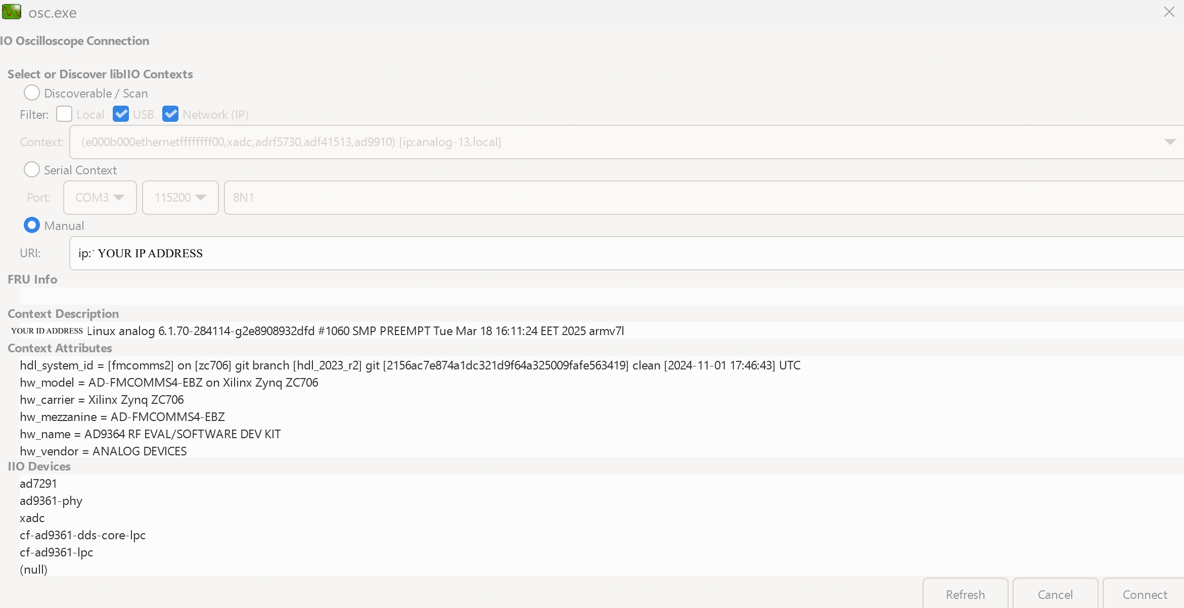
Once the application is launched, go to Settings > Connect > URI and type “ip:” then the IP address of the target in the pop-up window. This IP can be found out with a command from the previous section of this documentation.
Locally run on the board
If you connected an HDMI monitor to your FPGA and a mouse and a keyboard (both on one dongle), you can navigate the ADI Kuiper Linux that is on the FPGA.
Going to the top left corner icon (the menu icon), search for IIO Oscilloscope. Opening it will automatically connect to the setup and you can use the application.
For no-OS
For connecting IIO Oscilloscope to no-OS applications, they need to be built with the IIOD=y flag. This way, the no-OS applications will run an IIO daemon that is awaiting connections from the IIO Oscilloscope.
As indicated in the boot log, the board runs an IIOD server over the serial (UART) connection.
Disconnect or close the serial terminal used to view the boot log.
Once done with the installation or an update of the latest IIO Oscilloscope, open the application.
Select the Serial backend and configure the connection with the settings shown at the end of the boot log.
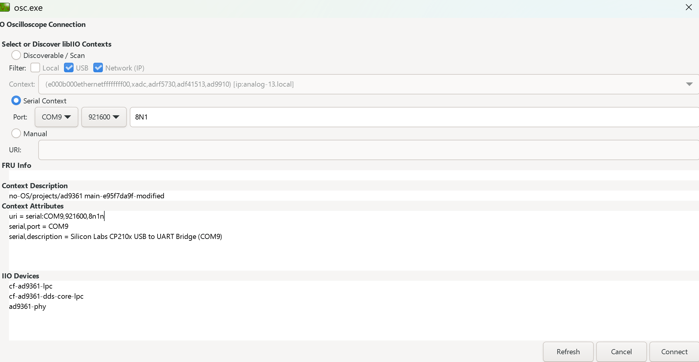
Press Refresh to display the available IIO devices and press Connect.
Note
The serial port is the COM port on Windows or /dev/ttyUSBx on Linux.
Plugin
This project also contains an IIO-Oscilloscope device-specific plugin that enables you to access the unique features and functions of the device.
See also
For more information about this plugin: AD936X Plugin Description
Data capture
Note
Device names and channel definition may differ between no-OS and Linux.
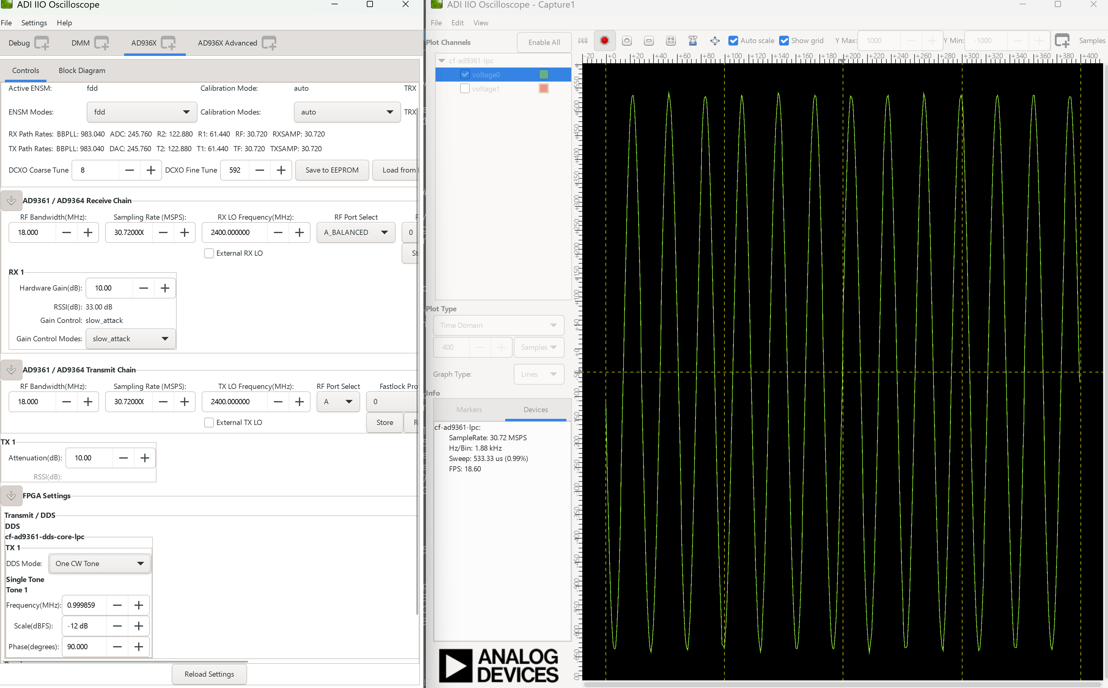
Time domain: