2-24 GHz reference design hardware prototyping
This page details the prototype hardware that ADI developed to prove out and prototype this reference design. The hardware is composed of 2 main platforms:
2 to 24 GHz RX Engineering Platform
2 to 24 GHz TX Engineering Platform
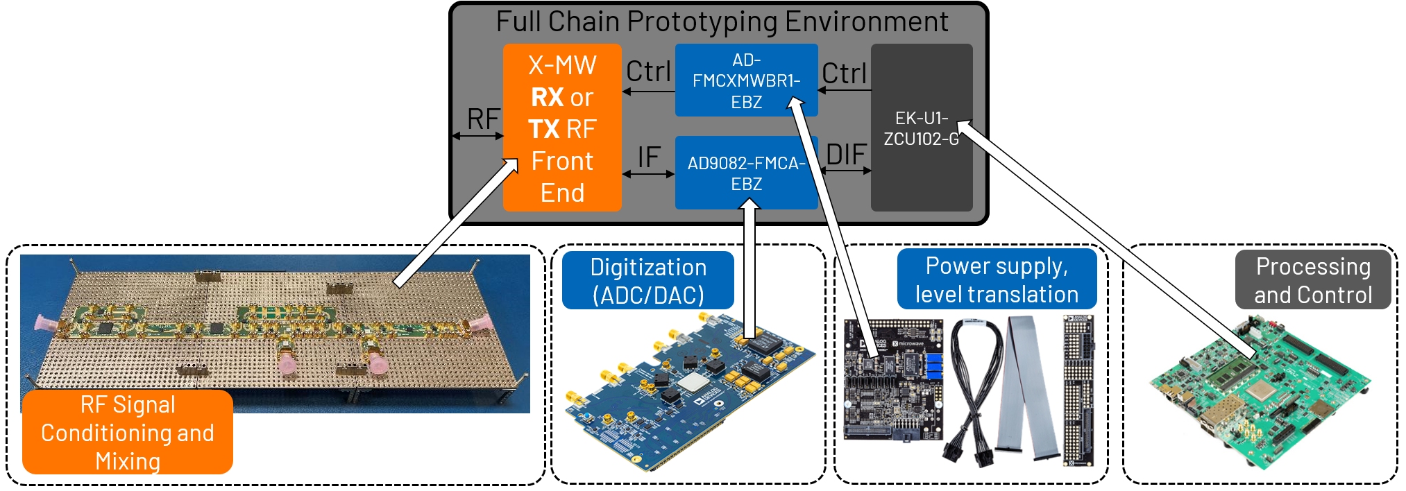
Each platform is composed of 4 primary pieces of hardware:
X-Microwave RF Signal Chain (X-Microwave Reference Design Kits)
AD9082 Evaluation Board (AD9082-FMCA-EBZ)
ZCU102 Evaluation Board (EK-U1-ZCU102-G)
ADI’s X-Microwave Bridge Board (AD-FMCXMWBR1-EBZ)
Additional hardware is also needed, such as cables, test equipment and power supplies.
With these 4 key pieces of hardware, the full signal chain (including the digitizer) can be evaluated for functionality and performance. Additionally, all control of the signal chain is conducted from a central location (FPGA on the ZCU102), which allows for coordinated control system prototyping.
Below is a diagram showing how these pieces fit together to complete the prototyping system.
Once the hardware is connected as pictured above, the pinouts for the XMW bridge board can be distributed to the components in the signal chain to interface with the hardware platform. The following block diagram shows the receiver signal chain with LO circuits and XMW bridge board pinouts connected:
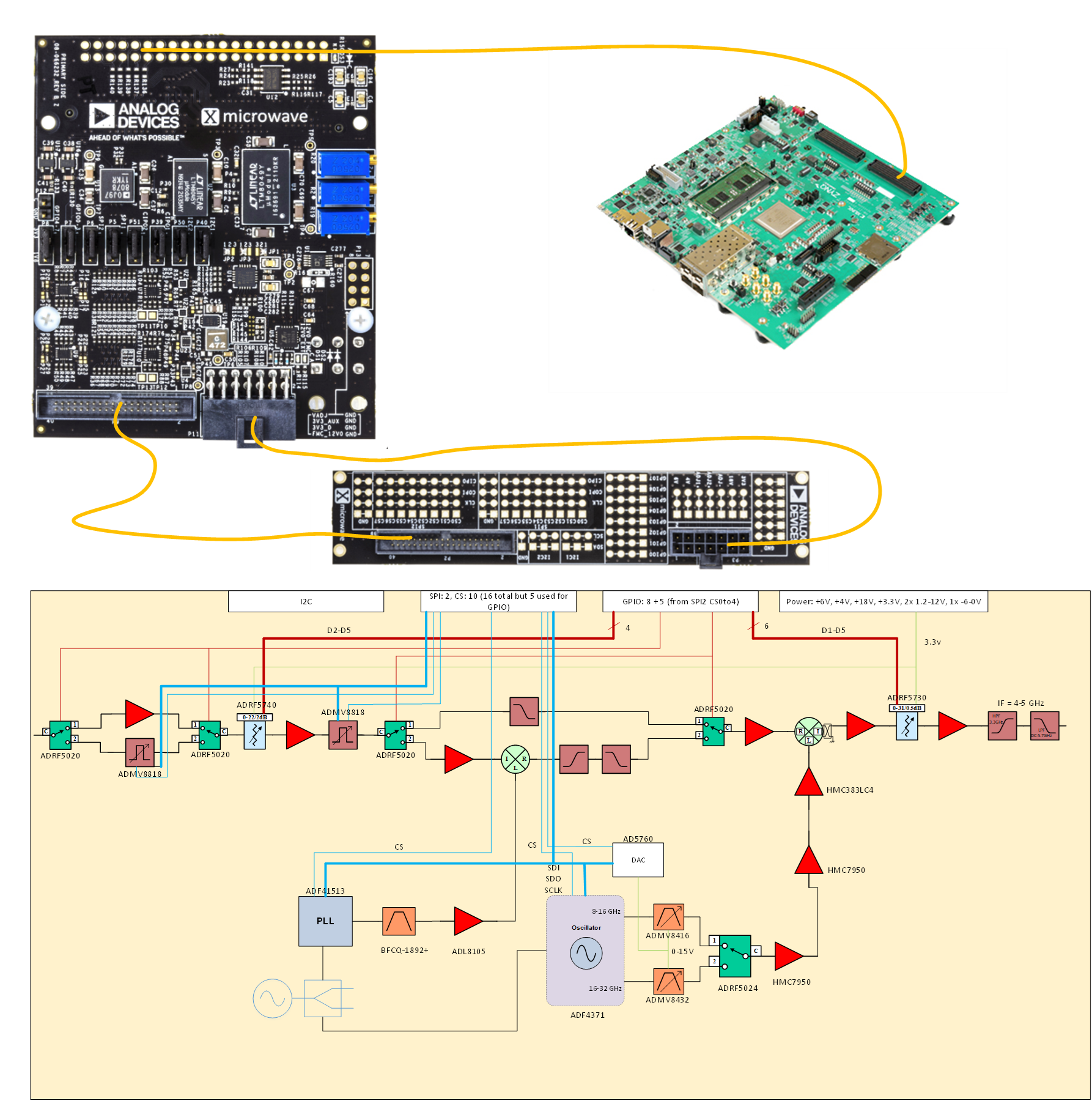
Figure 2 Receiver signal chain with XMW bridge board pinouts
The following block diagram shows the transmit signal chain with LO circuits and XMW bridge board pinouts connected:
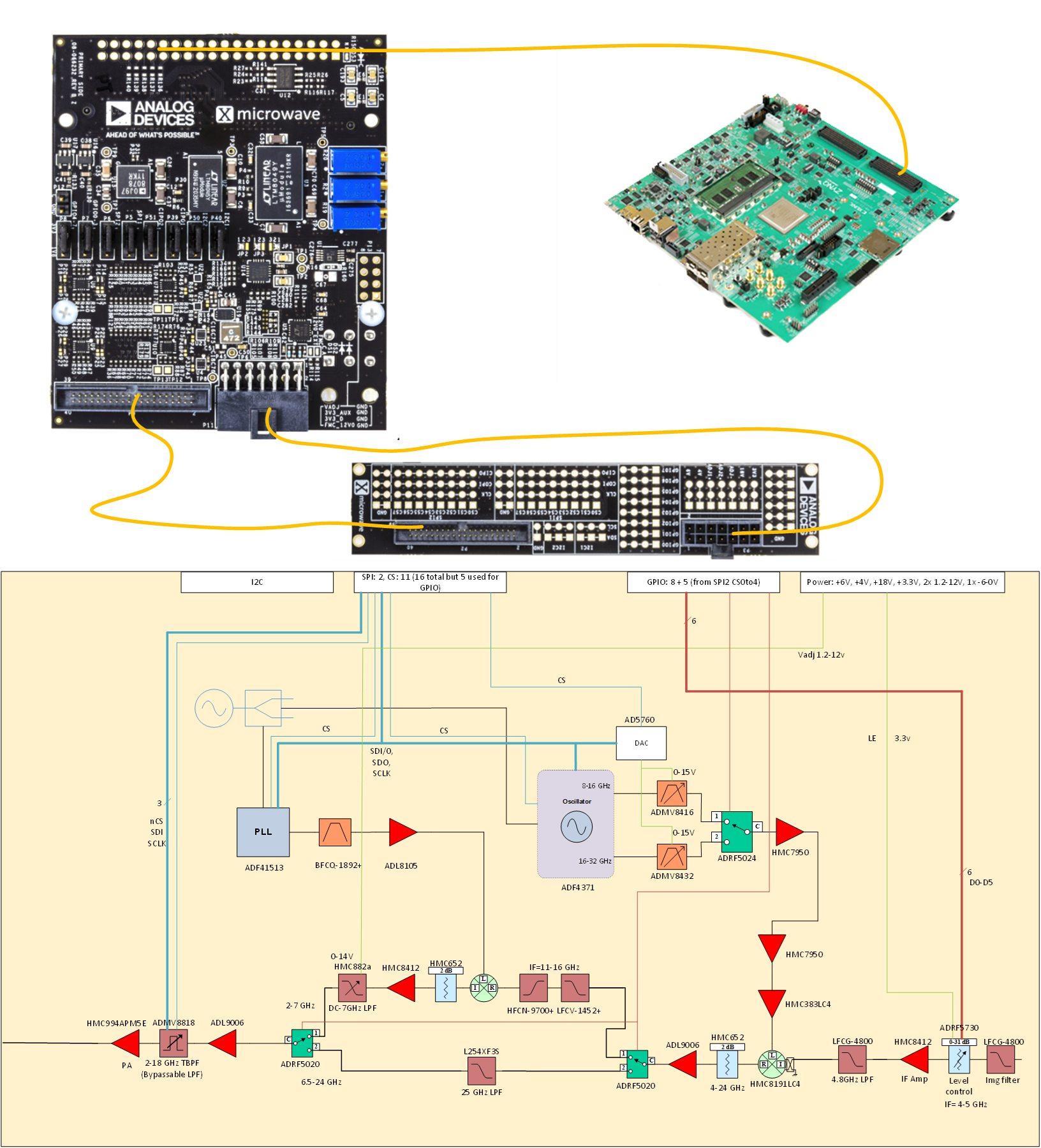
Figure 3 Transmit signal chain with XMW bridge board pinouts
Important
This hardware is currently in development. We expect to have results of our prototyping posted soon.