ZCU102 Quickstart
All the products described on this page include ESD (electrostatic discharge) sensitive devices. Electrostatic charges as high as 4000V readily accumulate on the human body or test equipment and can discharge without detection. Although the boards feature ESD protection circuitry, permanent damage may occur on devices subjected to high-energy electrostatic discharges. Therefore, proper ESD precautions are recommended to avoid performance degradation or loss of functionality. This includes removing static charge on external equipment, cables, or antennas before connecting to the device.
This guide provides quick instructions on how to setup the EVAL-ADRV904x on:
ZCU102 on FMC HPC0 using FMC extender standard SAMTEC
Using Linux as software
Necessary files
Note
The SD card includes several folders in the root directory of the BOOT partition. In order to configure the SD card to work with a specific FPGA board and ADI hardware, several files must be copied onto the root directory. Using the host PC, drag and drop the required files onto the BOOT partition, and use the EJECT function when removing the SD card from the reader.
The following files are needed for the system to boot:
HDL boot image:
BOOT.BINLinux Kernel image:
ImageLinux device tree:
system.dtb
They can either be taken from the SD card – already generated by us, or you can build them manually:
Instructions on how to choose the boot files from the SD card can be found in the Platform-Specific Manual Steps section from here: Hardware Configuration.
Instructions on how to manually build the boot files from source can be found here:
ADRV904x HDL reference design build documentation. More HDL build details at Build an HDL project.
Important
Some projects provide multiple devicetree files in the SD card’s boot folders. Make sure you select the devicetree that matches your specific use case.
Required Software
SD Card 16GB imaged with Kuiper (check out that guide on how to do it, then come back to this section)
A UART terminal (Putty/Tera Term/Minicom, etc.) with baud rate 115200 (8N1)
Required hardware
ZCU102 Rev 1.0 or later board and its power supply (12V)
EVAL-ADRV904x evaluation board
Micro-USB cable (UART)
LAN cable (Ethernet)
(Optional) USB keyboard & mouse and a DisplayPort compatible monitor
More details as to why you need these can be found at Prerequisites.
Testing
Creating the setup
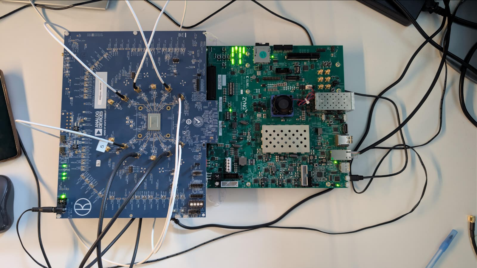
The photograph below shows the complete Linux hardware setup, including the ZCU102 board with the EVAL-ADRV904x connected to the FMC HPC0 port, along with all required cables:
Tip
Three jumpers must be mounted on the EVAL-ADRV904x board on the following headers with the following settings:
P209 - GPIO4_FMC
P216 - GPIO11_FMC
P2021 - TEST connected to GND
Follow the steps in this order, to avoid damaging the components:
Connect the EVAL-ADRV904x FMC board to the FPGA carrier HPC0 FMC socket using FMC extender standard SAMTEC
Insert SD card into the SD card socket on the FPGA
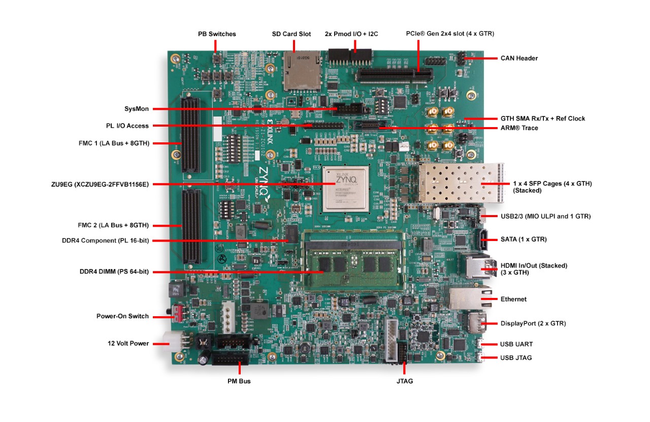
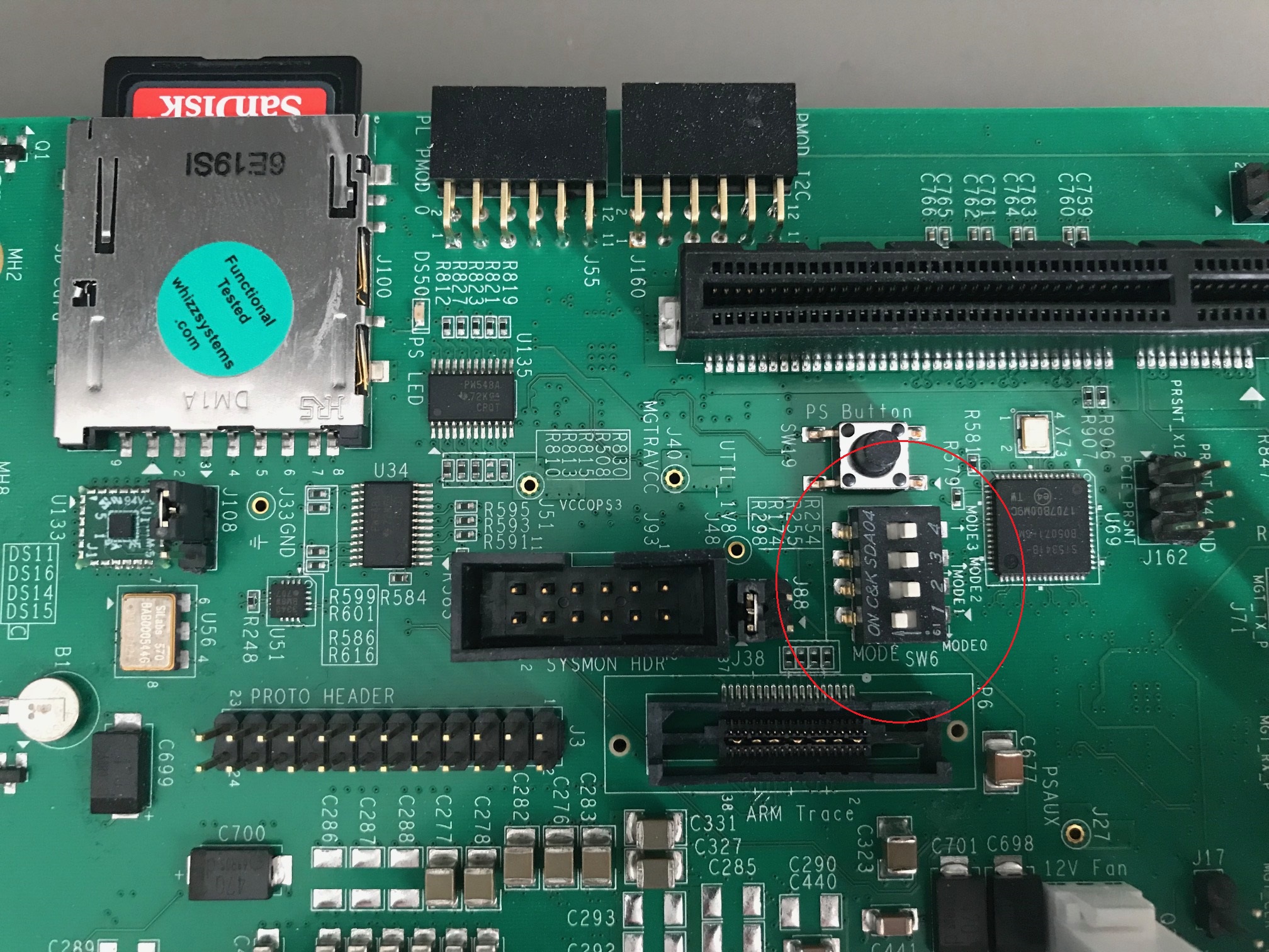
Configure ZCU102 for SD card boot mode (mode SW6[4:1] switch in the position OFF,OFF,OFF,ON as seen in the below picture)
Plug-in an Ethernet cable from your router/switch to the Ethernet port on the FPGA board
Connect USB UART J83 (Micro USB) to your host PC
(Optional) Connect a monitor to the FPGA by DisplayPort, and a mouse and a keyboard
Connect the power supply for the FPGA
Turn on the power switch on the FPGA board
Observe Kernel and serial console output messages on your terminal (use the first ttyUSB or COM port registered)
Boot messages
The following is what is printed in the serial console, after you have connected to the proper ttyUSB or COM port:
Zynq MP First Stage Boot Loader
Release 2025.1   Dec  9 2025  -  14:14:37
NOTICE:  BL31: Non secure code at 0x8000000
NOTICE:  BL31: v2.12.0(release):xilinx-v2025.1
NOTICE:  BL31: Built : 11:08:56, Aug 12 2025
PMUFW:  v1.1


U-Boot 2018.01-21442-gf06dec3cab (Feb 13 2025 - 17:12:07 +0200) Xilinx ZynqMP ZCU102 revA

I2C:   ready
DRAM:  4 GiB
EL Level:       EL2
Chip ID:        zu9eg
MMC:   sdhci@ff170000: 0 (SD)
*** Warning - bad CRC, using default environment

In:    serial@ff000000
Out:   serial@ff000000
Err:   serial@ff000000
Bootmode: LVL_SHFT_SD_MODE1
Net:   ZYNQ GEM: ff0e0000, phyaddr 15, interface rgmii-id

Warning: ethernet@ff0e0000 using MAC address from ROM
eth0: ethernet@ff0e0000
Hit any key to stop autoboot:  0
switch to partitions #0, OK
mmc0 is current device
...
reading Image
44519936 bytes read in 2980 ms (14.2 MiB/s)
## Flattened Device Tree blob at 04000000
   Booting using the fdt blob at 0x4000000
   Loading Device Tree to 000000000fff0000, end 000000000ffff0f4 ... OK

Starting kernel ...

[    0.000000] Booting Linux on physical CPU 0x0000000000 [0x410fd034]
[    0.000000] Linux version 6.12.0-27064-g9495a3d76542 (spopa@HYB-JRXo5UEs61B) #16 SMP Tue Feb 17 17:01:10 EET 2026
[    0.000000] Machine model: ZynqMP ZCU102 Rev1.0
[    0.000000] earlycon: cdns0 at MMIO 0x00000000ff000000 (options '115200n8')
...
[    1.017619] jesd204: created con: id=0, topo=0, link=0, /axi/spi@ff040000/ad9528-1@1 <-> /fpga-axi@0/axi-adxcvr-tx@84a80000
[    1.028155] jesd204: created con: id=1, topo=0, link=2, /axi/spi@ff040000/ad9528-1@1 <-> /fpga-axi@0/axi-adxcvr-rx@84a60000
[    1.039223] jesd204: created con: id=2, topo=0, link=0, /fpga-axi@0/axi-adxcvr-tx@84a80000 <-> /fpga-axi@0/axi-jesd204-tx@84a90000
[    1.050895] jesd204: created con: id=3, topo=0, link=2, /fpga-axi@0/axi-adxcvr-rx@84a60000 <-> /fpga-axi@0/axi-jesd204-rx@84aa0000
[    1.062597] jesd204: created con: id=4, topo=0, link=0, /fpga-axi@0/axi-jesd204-tx@84a90000 <-> /fpga-axi@0/axi-adrv904x-tx-hpc@84a04000
[    1.074788] jesd204: created con: id=5, topo=0, link=2, /fpga-axi@0/axi-jesd204-rx@84aa0000 <-> /axi/spi@ff040000/adrv904x-phy@0
[    1.086273] jesd204: created con: id=6, topo=0, link=0, /fpga-axi@0/axi-adrv904x-tx-hpc@84a04000 <-> /axi/spi@ff040000/adrv904x-phy@0
[    1.098218] jesd204: /axi/spi@ff040000/adrv904x-phy@0: JESD204[0:0] transition uninitialized -> initialized
[    1.107895] jesd204: /axi/spi@ff040000/adrv904x-phy@0: JESD204[0:2] transition uninitialized -> initialized
[    1.117583] jesd204: found 7 devices and 1 topologies
...
[    1.940648] axi_sysid 85000000.axi-sysid-0: [adrv904x] [JESD_MODE=64B66B RX:RATE=24.33 M=8 L=4 S=1 NP=16 TPL_WIDTH= LINKS=1 TX:RATE=24.33 M=8 L=4 S=1 NP=16 TPL_WIDTH= LINKS=1] on [zcu102]
...
[   29.767179] systemd[1]: Failed to look up module alias 'autofs4': Function not implemented
[   29.800681] systemd[1]: systemd 247.3-7+rpi1+deb11u2 running in system mode.

Welcome to Kuiper GNU/Linux 11.2 (bullseye)!

...
My IP address is 192.168.100.2 169.254.173.46

Raspbian GNU/Linux 11 analog ttyPS0

analog login:
Useful commands for the serial terminal
The below commands are to be run in the serial terminal connected to the FPGA.
Login Information
Default login credentials:
Username:
analogPassword:
analog
To find out the IP of the FPGA board, run the following command and take the IP specified at “eth0 inet”:
~$
ifconfig
To see the IIO devices detected, run:
~$
iio_info | grep iio:device
iio:device0: xilinx-ams
iio:device1: adrv904x-phy
iio:device2: axi-adrv904x-rx-hpc (buffer capable)
iio:device3: axi-adrv904x-tx-hpc (buffer capable)
To use the JESD204 status utility, run:
~$
jesd_status
Additionally, if running stty rows 30 before running jesd_status, you
can expand the visible area of it and see more than 4 lanes.
To power off the system, run the following command, and wait for the final message to be printed, then power off the FPGA board from the switch as well.
~$
poweroff
To reboot the system, run:
~$
reboot
Important
Even thought this is Linux, this is a persistent file systems. Care should be
taken not to corrupt the file system – please shut down things, don’t just
turn off the power switch. Depending on your monitor, the standard power off
could be hiding. You can do this from the terminal as well with sudo
shutdown -h now or the above-mentioned command for powering off.
Verifying the setup
For a detailed overview of the setup verification using IIO Oscilloscope , see IIO OSC ADRV904x Capture Window.
Using no-OS as software
Necessary files
The following files are needed for the system to boot:
HDL boot file:
system_top.xsano-OS project: projects/adrv904x
More no-OS build details at No-OS Build Guide.
Instructions on how to build the boot files from source can be found here:
More HDL build details at Build an HDL project.
Required Software
AMD Xilinx Vivado and Vitis (downloading Vitis from here will include Vivado as well)
An UART terminal (Putty/Tera Term/Minicom, etc.), Baud rate 115200 (8N1)
Required Hardware
AMD Xilinx ZCU102 Rev 1.0 FPGA board and its power supply
EVAL-ADRV904x FMC evaluation board
2x Micro-USB cables, one for UART and one for JTAG
(Optional) USB keyboard & mouse and a DisplayPort-compatible monitor
More details as to why you need these, can be found at Prerequisites.
Testing
Creating the setup
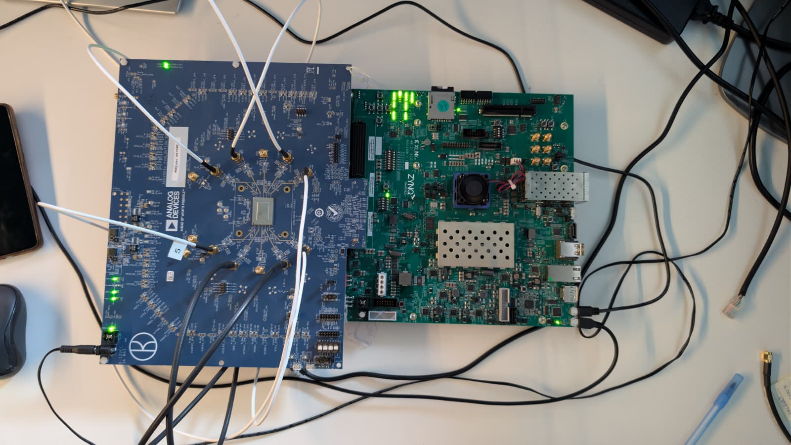
The photograph below shows the complete no-OS hardware setup, including the ZCU102 board with the EVAL-ADRV904x connected to the FMC HPC0 port, along with all required cables:
Follow the steps in this order, to avoid damaging the components:
Connect the EVAL-ADRV904x FMC board to the ZCU102 HPC0 FMC socket using FMC extender standard SAMTEC
Configure ZCU102 for JTAG boot mode (mode SW6[4:1] switch in the position ON,ON,ON,ON)
Connect USB UART J83 (Micro-USB) to your host PC
Connect USB JTAG J2 (Micro-USB) to your host PC
(Optional) Connect a monitor to the FPGA by DisplayPort, and a mouse and a keyboard
Turn on the power switch on the FPGA board
Observe the boot output on the UART terminal
Demo applications
Three demo applications are available in the no-OS project, selected via Makefile variables:
Basic example: Initializes all components and enables the JESD204 link. The transmitter outputs a DDS waveform with default parameters.
DMA example: Transmits sinewave patterns via DMA from lookup tables and captures receive data to memory for analysis (exportable as CSV).
IIO example: Launches an IIOD server on the board, allowing connection via an IIO client such as IIO Oscilloscope to configure the transceiver and capture data. The IIOD server runs at 921600 baud.
Only one example can be active at a time.
Console output
A successful boot produces the following output on the UART terminal:
Zynq MP First Stage Boot Loader
Release 2025.2   Mar 23 2026  -  14:57:47

PMU-FW is not running, certain applications may not be supported.

rx_adxcvr: Using QPLL with previously defined settings.

Firmware file: ADRV9040_FW.bin
Gain Table file: RxGainTable.csv
Streams file: stream_image.bin
Device Profile file: DeviceProfileTest.bin
DFE file: ADRV9040_DFE_CALS_FW.bin
Radio Sequencer file:

adrv904x_setup()

adrv904x-phy Rev 0, API version: 2.15.0.4 found
adrv904x-device revision: 0xa0
Using the Profile Init and PostMcsInit Structures

rx_clkgen: MMCM-PLL locked (245760000 Hz)
tx_clkgen: MMCM-PLL locked (245760000 Hz)
tx_dac: Successfully initialized (491519165 Hz)
tx_adxcvr: OK (16220160 kHz)
rx_adxcvr: OK (16220160 kHz)

Link0 deframerStatus linkState 0x3
WARNING: Link0 deframerStatus 0 laneStatus 0xE
WARNING: Link0 deframerStatus 1 laneStatus 0xE
WARNING: Link0 deframerStatus 2 laneStatus 0xE
WARNING: Link0 deframerStatus 3 laneStatus 0xE
WARNING: Link0 deframerStatus 4 laneStatus 0xE
WARNING: Link0 deframerStatus 5 laneStatus 0xE
WARNING: Link0 deframerStatus 6 laneStatus 0xE
WARNING: Link0 deframerStatus 7 laneStatus 0xE

adrv904x-phy Rev 160, API version: 2.15.0.4

tx_jesd status:
Link is enabled
Measured Link Clock: 245.758 MHz
Reported Link Clock: 245.760 MHz
Lane rate: 16220.160 MHz
Lane rate / 66: 245.760 MHz
LEMC rate: 7.680 MHz
Link status: DATA
SYSREF captured: Yes
SYSREF alignment error: No

rx_jesd status:
Link is enabled
Measured Link Clock: 245.760 MHz
Reported Link Clock: 245.760 MHz
Lane rate: 16220.160 MHz
Lane rate / 66: 245.760 MHz
LEMC rate: 7.680 MHz
Link status: DATA
SYSREF captured: Yes
SYSREF alignment error: No
Zynq MP First Stage Boot Loader
Release 2025.2   Mar 23 2026  -  14:57:47

PMU-FW is not running, certain applications may not be supported.

rx_adxcvr: Using QPLL with previously defined settings.

Firmware file: ADRV9040_FW.bin
Gain Table file: RxGainTable.csv
Streams file: stream_image.bin
Device Profile file: DeviceProfileTest.bin
DFE file: ADRV9040_DFE_CALS_FW.bin
Radio Sequencer file:

adrv904x_setup()

adrv904x-phy Rev 0, API version: 2.15.0.4 found
adrv904x-device revision: 0xa0
Using the Profile Init and PostMcsInit Structures

rx_clkgen: MMCM-PLL locked (245760000 Hz)
tx_clkgen: MMCM-PLL locked (245760000 Hz)
tx_dac: Successfully initialized (491516113 Hz)
tx_adxcvr: OK (16220160 kHz)
rx_adxcvr: OK (16220160 kHz)

Link0 deframerStatus linkState 0x3
WARNING: Link0 deframerStatus 0 laneStatus 0xE
WARNING: Link0 deframerStatus 1 laneStatus 0xE
WARNING: Link0 deframerStatus 2 laneStatus 0xE
WARNING: Link0 deframerStatus 3 laneStatus 0xE
WARNING: Link0 deframerStatus 4 laneStatus 0xE
WARNING: Link0 deframerStatus 5 laneStatus 0xE
WARNING: Link0 deframerStatus 6 laneStatus 0xE
WARNING: Link0 deframerStatus 7 laneStatus 0xE

adrv904x-phy Rev 160, API version: 2.15.0.4

tx_jesd Link is enabled
Measured Link Clock: 245.758 MHz
Reported Link Clock: 245.760 MHz
Lane rate: 16220.160 MHz
Lane rate / 66: 245.760 MHz
LEMC rate: 7.680 MHz
Link status: DATA
SYSREF captured: Yes
SYSREF alignment error: No

rx_jesd status:
Link is enabled
Measured Link Clock: 245.760 MHz
Reported Link Clock: 245.760 MHz
Lane rate: 16220.160 MHz
Lane rate / 66: 245.760 MHz
LEMC rate: 7.680 MHz
Link status: DATA
SYSREF captured: Yes
SYSREF alignment error: No

Running IIOD server...

If successful, you may connect an IIO client application by:
1. Disconnecting the serial terminal you use to view this message.
2. Connecting the IIO client application using the serial backend
   configured as shown:
   Baudrate: 921600
   Data size: 8 bits
   Parity: none
   Stop bits: 1
   Flow control: none
Zynq MP First Stage Boot Loader
Release 2025.2   Mar 23 2026  -  14:57:47

PMU-FW is not running, certain applications may not be supported.

rx_adxcvr: Using QPLL with previously defined settings.

Firmware file: ADRV9040_FW.bin
Gain Table file: RxGainTable.csv
Streams file: stream_image.bin
Device Profile file: DeviceProfileTest.bin
DFE file: ADRV9040_DFE_CALS_FW.bin
Radio Sequencer file:

adrv904x_setup()

adrv904x-phy Rev 0, API version: 2.15.0.4 found
adrv904x-device revision: 0xa0
Using the Profile Init and PostMcsInit Structures

rx_clkgen: MMCM-PLL locked (245760000 Hz)
tx_clkgen: MMCM-PLL locked (245760000 Hz)
tx_dac: Successfully initialized (491519165 Hz)
tx_adxcvr: OK (16220160 kHz)
rx_adxcvr: OK (16220160 kHz)

Link0 deframerStatus linkState 0x3
WARNING: Link0 deframerStatus 0 laneStatus 0xE
WARNING: Link0 deframerStatus 1 laneStatus 0xE
WARNING: Link0 deframerStatus 2 laneStatus 0xE
WARNING: Link0 deframerStatus 3 laneStatus 0xE
WARNING: Link0 deframerStatus 4 laneStatus 0xE
WARNING: Link0 deframerStatus 5 laneStatus 0xE
WARNING: Link0 deframerStatus 6 laneStatus 0xE
WARNING: Link0 deframerStatus 7 laneStatus 0xE

adrv904x-phy Rev 160, API version: 2.15.0.4

tx_jesd status:
Link is enabled
Measured Link Clock: 245.758 MHz
Reported Link Clock: 245.760 MHz
Lane rate: 16220.160 MHz
Lane rate / 66: 245.760 MHz
LEMC rate: 7.680 MHz
Link status: DATA
SYSREF captured: Yes
SYSREF alignment error: No

rx_jesd status:
Link is enabled
Measured Link Clock: 245.758 MHz
Reported Link Clock: 245.760 MHz
Lane rate: 16220.160 MHz
Lane rate / 66: 245.760 MHz
LEMC rate: 7.680 MHz
Link status: DATA
SYSREF captured: Yes
SYSREF alignment error: No

DMA_EXAMPLE Tx: address=0x434c00 samples=8192 channels=16 bits=32
DMA_EXAMPLE Rx: address=0x3b4c00 samples=262144 channels=16 bits=16
Verifying the setup
For a detailed overview of the setup verification using IIO Oscilloscope , see IIO OSC ADRV904x Capture Window.
Switching between use cases
Since no-OS runs bare-metal without a file system, all profile and firmware data is compiled into the binary as C headers in firmware dir.
The entire device configuration for a given use case is contained in the profile
binary (DeviceProfileTest.bin), which is generated using the ADI evaluation
software (see the ADRV904x Evaluation System User Guide). The stream image
(stream_image.bin) is also specific to a configuration. The firmware files
(ADRV9040_FW.bin, ADRV9040_DFE_CALS_FW.bin) are typically static and
supplied by ADI.
Radio control and JESD204 parameters (LO frequencies, channel masks, lane rates)
are set directly in
initdata.c
as C structs (deviceInitStruct, utilityInit).
To switch to a different use case:
Generate the new
DeviceProfileTest.binandstream_image.binusing the ADI evaluation software.Convert each binary to a C header using
xxd:xxd -i DeviceProfileTest.bin > DeviceProfileTest.h xxd -i stream_image.bin > stream_image.h
Copy the generated headers into firmware dir, replacing the existing files.
If radio control or JESD204 parameters also changed, update the corresponding fields in
initdata.c(deviceInitStructandutilityInit).Rebuild the project.