AD-DYNO2-EBZ Dynamometer Drive System
Features
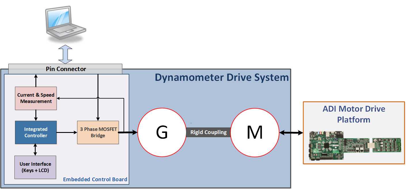
Two BLDC motors connected in a dyno setup (BLY171S-24V-4000 and BLY171D-24V-4000)
Electronically adjustable load - the load value is set using the onboard buttons and LCD
Programmable step and ramp load changes
Measurement and display of load motor phase currents
Measurement and display of load motor speed
Block Diagram
Key Parts
Part |
Description |
|---|---|
Power |
|
isoPower® integrated isolated dc-to-dc converter |
|
High accuracy ultralow quiescent current, 500 mA, AnyCAP® LDO |
|
Isolation |
|
3 kV RMS isolated precision half-bridge driver, 4 A output |
|
Control |
|
Precision Analog Microcontroller, 12-bit Analog I/O, ARM7TDMI MCU |
User Guide
The system is equipped with an LCD which displays information about the state of the load. Together with the 3 push buttons placed below it, the LCD is used to display and configure different system parameters. The +/- buttons navigate through the system menu and change system parameters. The Enter button confirms parameter changes or enters / exits the menu screens.
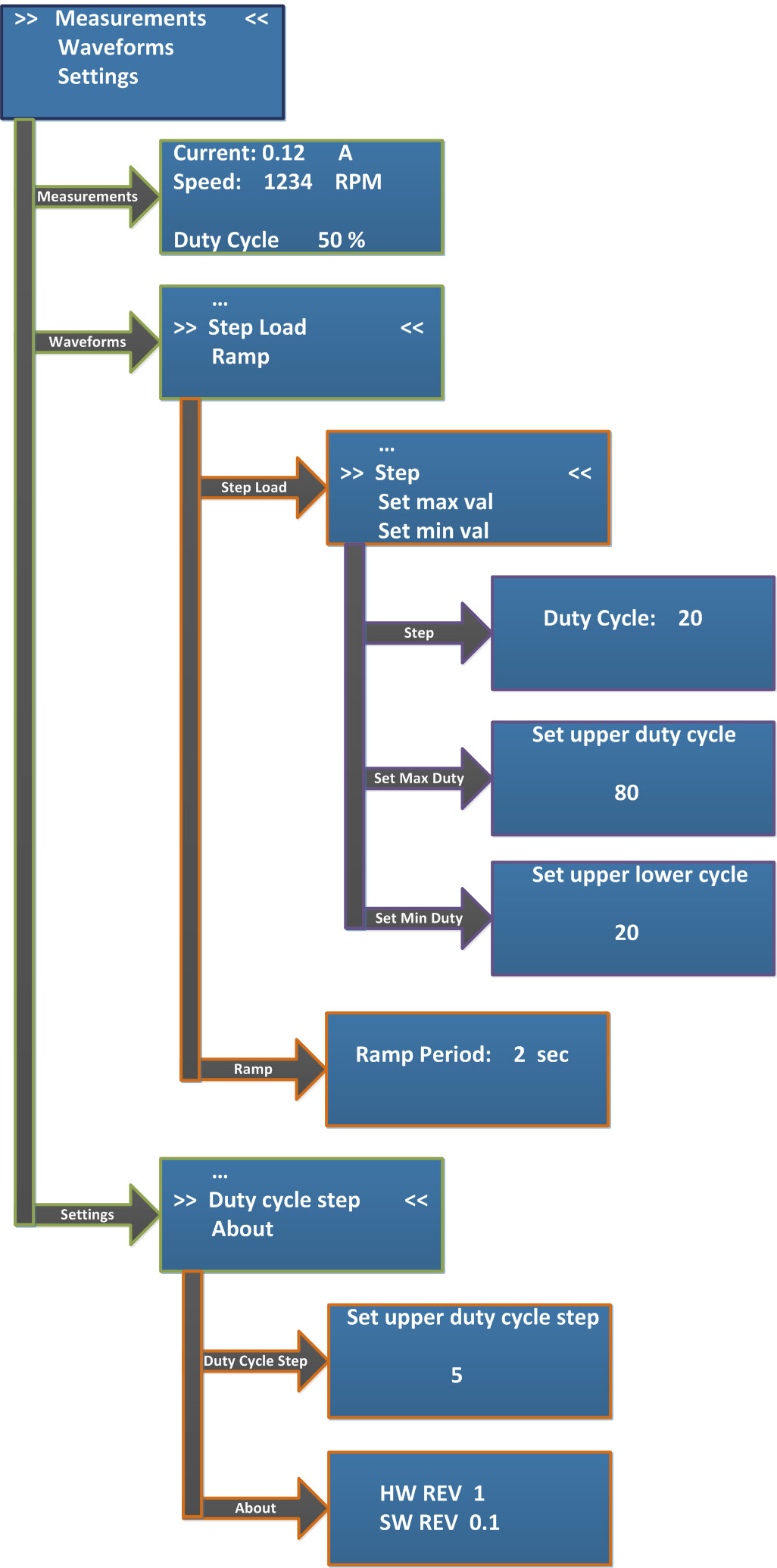
Main menu is displayed at power up.
The measurement menu displays RMS phase currents and motor speed. The load can be adjusted by pressing the “+” or “-” buttons. Press “Enter” to return to the main menu.
Waveforms menu. Select ramp or step load. Select “…” and press “Enter” to go back.
Step load menu. Select “Step” to start toggling the load.
Press “+” or “-” to toggle between the preset step values. Press “Enter” to go back.
Set maximum duty cycle. Press “Enter” to go back.
Set minimum duty cycle. Press “Enter” to go back.
Ramp load menu. Press “+” or “-” to change ramp period. Press “Enter” to go back.
Settings menu. Select “…” and press “Enter” to go back.
Change duty cycle step.
About.
External Control
To interface the Dyno with an external control system:
Slide switch S2 to EXT_CTRL position
Connect to header P1
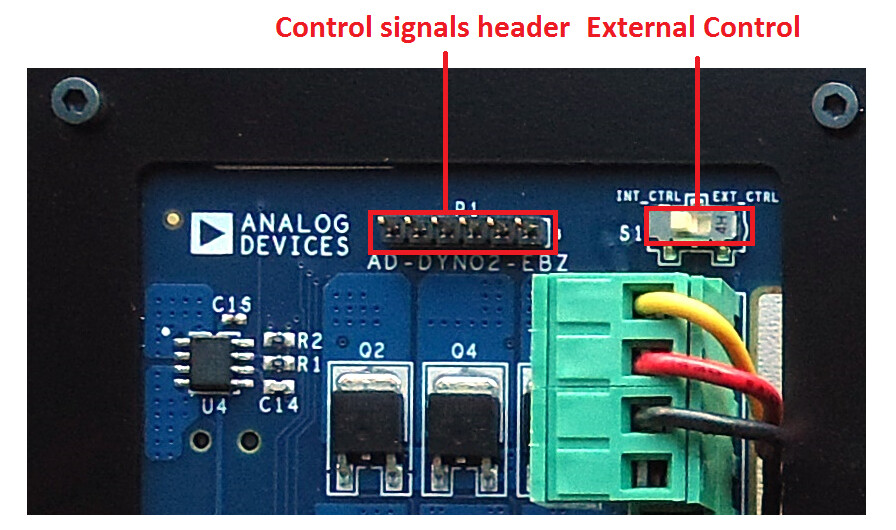
The available external signals are:
Dyno Signal |
Description |
|---|---|
I_A |
Phase A motor current (185 mV/A) |
I_B |
Phase B motor current (185 mV/A) |
PWM1 |
Phase A PWM (3.3 V levels) |
PWM2 |
Phase B PWM (3.3 V levels) |
PWM3 |
Phase C PWM (3.3 V levels) |
Warning
The system needs a 5 V 500 mA power supply. The power connector is a 2.1 x 5.5 mm jack with the center pin positive (+).