User guide
Hardware guide
The motor control system consists of three boards that work together.
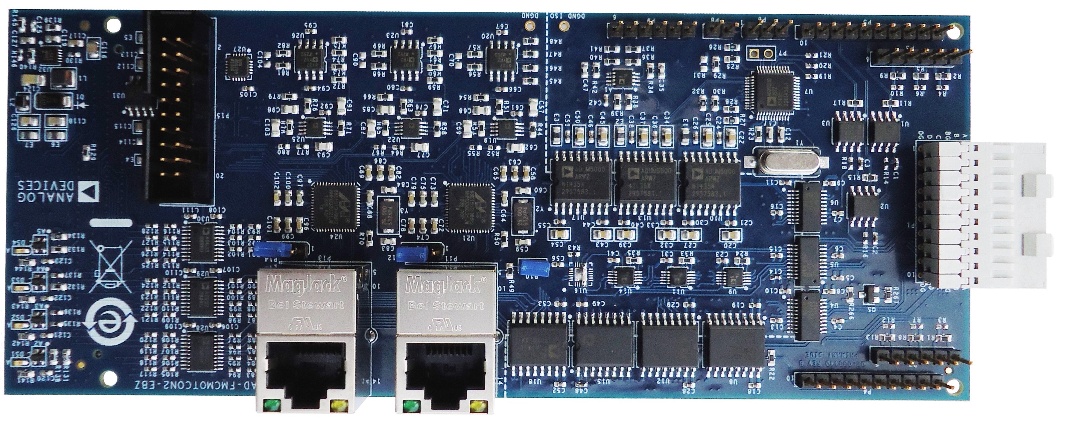
AD-FMCMOTCON2-EBZ - Controller board, compatible with all AMD Xilinx FPGA platforms with FMC LPC or HPC connectors.
2x Gbit Ethernet PHYs for high-speed industrial communication (RGMII)
Hall, Differential Hall, Encoder, and Resolver interfaces
EnDat and BISS digital sensor interfaces
Current and voltage measurement using isolated ADCs (AD7403)
Fully isolated control and feedback signals
AMD Xilinx XADC interface
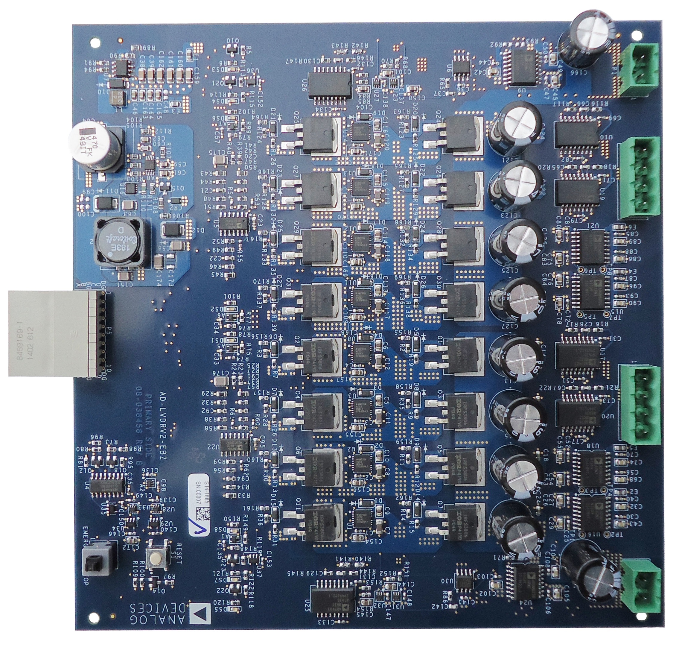
AD-DRVLV2-EBZ - Low voltage drive board. Connects to the Controller board with a power stage that drives Brushed DC / BLDC / PMSM / Stepper motors up to 48 V and 20 A.
Drives 2 motors simultaneously with independent power supplies
Integrated over-current and reverse voltage protection
Current and voltage measurement using isolated ADCs
BEMF zero-crossing detection for sensorless control
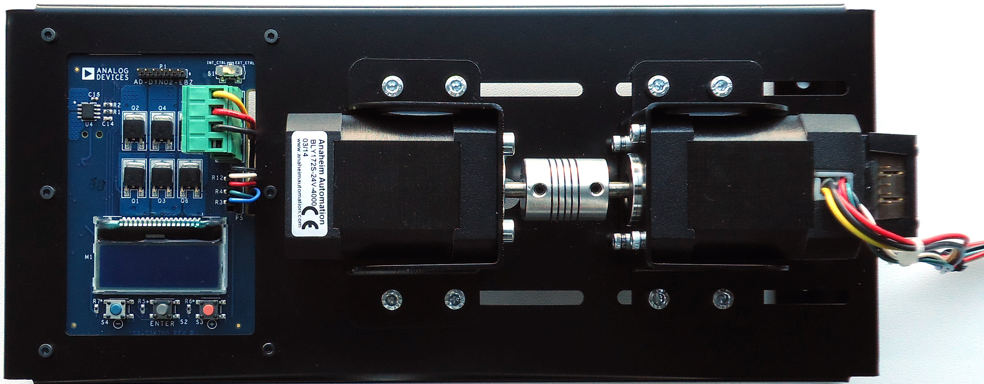
AD-DYNO2-EBZ - Dynamometer drive system (optional). An electronically adjustable load for testing real-time motor control performance.
Two BLDC motors connected in a dyno setup
Electronically adjustable load via onboard buttons and LCD
Programmable step and ramp load changes
Measurement and display of load motor phase currents and speed
External control via header P1
Additional hardware documentation:
Signal measurement chain - Ia/Ib and Vbus measurement chains with AD7403 isolated ΣΔ modulators and Sallen Key reconstruction filters; includes formulas for converting raw ADC codes to physical values.
Test procedure - Step-by-step procedure for FRU EEPROM programming, EtherCAT EEPROM, AD2S1210, and dyno functional testing.
Software guide
AMD Xilinx HDL Reference Design
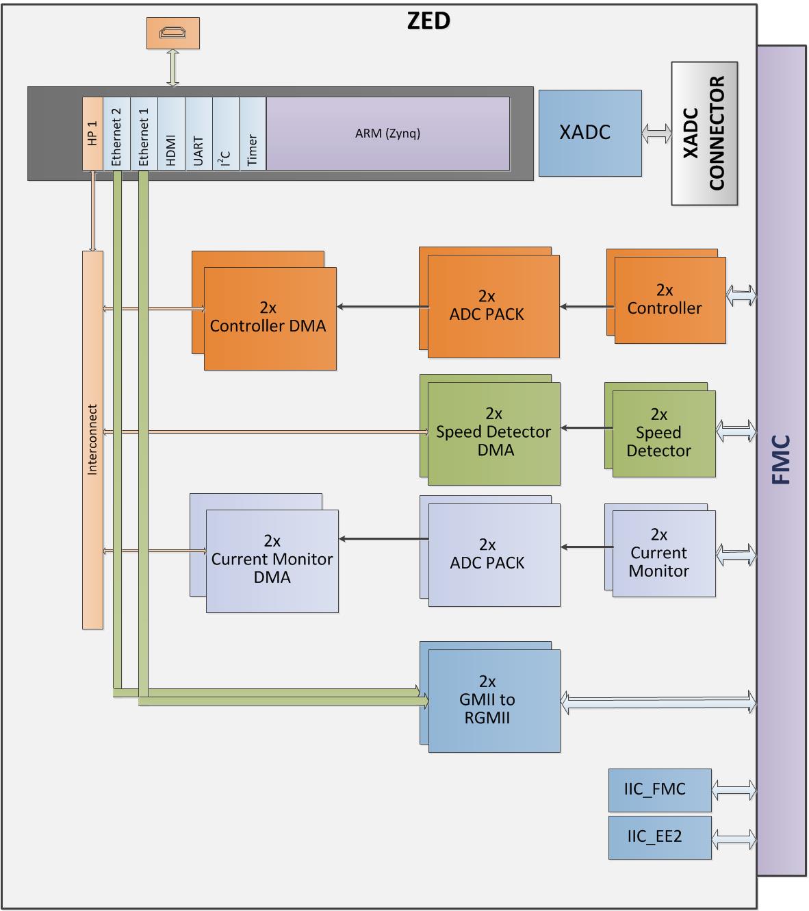
The reference design targets the ZedBoard and includes complete Linux infrastructure. The reference design contains HDL blocks for interfacing with the various components of the motor control hardware:
Current Monitor - Implements communication with the AD7401 sigma-delta modulators on the AD-FMCMOTCON2-EBZ, including the SINC3 filters for demodulating the 1-bit digital stream. Exposes AXI-Lite registers and a DMA interface for real-time data streaming to the application layer. An ADC PACK IP enables 1, 2, or all channels to stream data simultaneously.
Controller - Implements the interface to the IP control blocks in the system. A DMA interface allows real-time data streaming. Implements a basic six-point drive of the motor. An ADC PACK block enables 1, 2, 4, or all channels to stream data.
Speed Detector - Implements the algorithm for converting Hall, BEMF, and Encoder signals into speed and position data. Exposes AXI-Lite registers and a DMA interface.
GMII to RGMII - Converts the GMII interface from the two Ethernet cores in the PS7 block to the RGMII interface on the FMC Controller Board. Allows RX pins on different I/O banks.
I2C - Two I2C interfaces connected to the FMC board.
To build the project, follow the instructions from the ADI Reference Designs HDL User Guide.
Linux software
The software suite for Linux consists of:
Kuiper Linux - includes IIO subsystem drivers for the motor control solution (see driver table below).
IIO Oscilloscope - graphical monitoring and control of the motor drive system.
IIO drivers
The Linux Industrial I/O (IIO) subsystem provides support for devices that in some sense are analog-to-digital or digital-to-analog converters.
The IIO drivers for the motor control solution require the HDL cores to have a specified register map. A DMA interface is set up for high-speed data transfer using multiple multiplexed data channels.
IIO Driver |
Channel |
Description |
|---|---|---|
|
voltage0 |
Not used |
voltage1 |
Motor 1 Ia ADC raw data |
|
voltage2 |
Motor 1 Ib ADC raw data |
|
voltage3 |
Motor 1 VBus ADC raw data |
|
|
voltage0 |
Not used |
voltage1 |
Motor 2 Ia ADC raw data |
|
voltage2 |
Motor 2 Ib ADC raw data |
|
voltage3 |
Motor 2 VBus ADC raw data |
|
|
voltage0 |
Motor 1 speed. Number of counts in 10 ns units between two motor commutations. To display speed in RPM, enable the 1/x option and multiply by 25,000,000. |
|
voltage0 |
Motor 2 speed. Same scaling as ad-mc-speed. |
|
Not used |
|
|
Not used |
Each IIO driver has a device tree entry for the actual driver and an entry for the allocated DMA:
&fpga_axi {
    ad-mc-speed@40410000 {
        compatible = "xlnx,axi-ad-mc-speed-1.00.a";
        reg = <0x40410000 0x10000>;
        dmas = <&ad_mc_speed_dma 0>;
        dma-names = "ad-mc-speed-dma";
    };
    ad_mc_speed_dma: dma@40510000 {
        compatible = "adi,axi-dmac-1.00.a";
        reg = <0x40510000 0x10000>;
        #dma-cells = <1>;
        interrupts = <0 57 0>;
        clocks = <&clkc 15>;
        dma-channel {
            adi,buswidth = <32>;
            adi,type = <0>;
        };
    };

    ad-mc-adc@40420000 {
        compatible = "xlnx,axi-ad-mc-adc-1.00.a";
        reg = <0x40420000 0x10000>;
        dmas = <&ad_mc_adc_dma 0>;
        dma-names = "ad-mc-adc-dma";
    };
    ad_mc_adc_dma: dma@40520000 {
        compatible = "adi,axi-dmac-1.00.a";
        reg = <0x40520000 0x10000>;
        #dma-cells = <1>;
        interrupts = <0 54 0>;
        clocks = <&clkc 15>;
        dma-channel {
            adi,buswidth = <64>;
            adi,type = <0>;
        };
    };

    ad-mc-ctrl@40430000 {
        compatible = "xlnx,axi-ad-mc-ctrl-1.00.a";
        reg = <0x40430000 0x10000>;
        dmas = <&ad_mc_ctrl_dma 0>;
        dma-names = "ad-mc-ctrl-dma";
    };
    ad_mc_ctrl_dma: dma@40530000 {
        compatible = "adi,axi-dmac-1.00.a";
        reg = <0x40530000 0x10000>;
        #dma-cells = <1>;
        interrupts = <0 53 0>;
        clocks = <&clkc 15>;
        dma-channel {
            adi,buswidth = <256>;
            adi,type = <0>;
        };
    };

    ad-mc-speed-m2@40440000 {
        compatible = "xlnx,axi-ad-mc-speed-1.00.a";
        reg = <0x40440000 0x10000>;
        dmas = <&ad_mc_speed_dma_m2 0>;
        dma-names = "ad-mc-speed-dma";
    };
    ad_mc_speed_dma_m2: dma@40540000 {
        compatible = "adi,axi-dmac-1.00.a";
        reg = <0x40540000 0x10000>;
        #dma-cells = <1>;
        interrupts = <0 52 0>;
        clocks = <&clkc 15>;
        dma-channel {
            adi,buswidth = <32>;
            adi,type = <0>;
        };
    };

    ad-mc-adc-m2@40450000 {
        compatible = "xlnx,axi-ad-mc-adc-1.00.a";
        reg = <0x40450000 0x10000>;
        dmas = <&ad_mc_adc_dma_m2 0>;
        dma-names = "ad-mc-adc-dma";
    };
    ad_mc_adc_dma_m2: dma@40550000 {
        compatible = "adi,axi-dmac-1.00.a";
        reg = <0x40550000 0x10000>;
        #dma-cells = <1>;
        interrupts = <0 36 0>;
        clocks = <&clkc 15>;
        dma-channel {
            adi,buswidth = <64>;
            adi,type = <0>;
        };
    };

    ad-mc-ctrl-m2@40460000 {
        compatible = "xlnx,axi-ad-mc-ctrl-1.00.a";
        reg = <0x40460000 0x10000>;
        dmas = <&ad_mc_ctrl_dma_m2 0>;
        dma-names = "ad-mc-ctrl-dma";
    };
    ad_mc_ctrl_dma_m2: dma@40560000 {
        compatible = "adi,axi-dmac-1.00.a";
        reg = <0x40560000 0x10000>;
        #dma-cells = <1>;
        interrupts = <0 35 0>;
        clocks = <&clkc 15>;
        dma-channel {
            adi,buswidth = <256>;
            adi,type = <0>;
        };
    };
};

&spi0 {
    status = "okay";
    ad2s1210@0 {
        compatible = "ad2s1210";
        reg = <0>;
        spi-cpha;
        spi-max-frequency = <1000000>;
        sample-gpios = <&gpio 86 0>;
        adi,entirely-configuration-mode-enable;
    };
};
IIO Oscilloscope
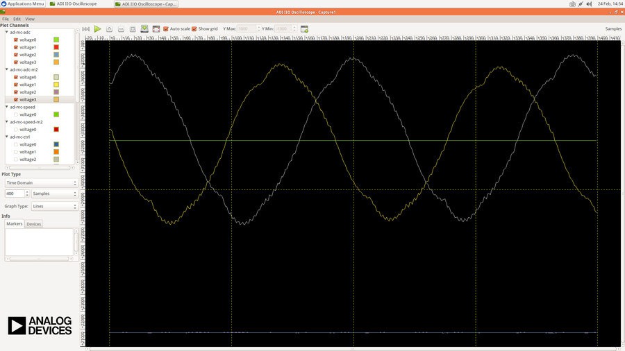
The IIO Oscilloscope is used for monitoring and controlling the AD-FMCMOTCON2-EBZ board when running Linux. It has two main sections: Capture for signal monitoring and Motor Control for manual control.
Signals monitoring (Capture)
The IIO Oscilloscope allows monitoring of current, voltage, speed, and control signals from the system.
Group |
Channel |
Description |
|---|---|---|
|
voltage0 |
Not used |
voltage1 |
Motor 1 Ia ADC raw data |
|
voltage2 |
Motor 1 Ib ADC raw data |
|
voltage3 |
Motor 1 VBus ADC raw data |
|
|
voltage0 |
Not used |
voltage1 |
Motor 2 Ia ADC raw data |
|
voltage2 |
Motor 2 Ib ADC raw data |
|
voltage3 |
Motor 2 VBus ADC raw data |
|
|
voltage0 |
Motor 1 speed. Enable 1/x and multiply by 25,000,000 to get RPM. |
|
voltage0 |
Motor 2 speed. Same scaling as ad-mc-speed. |
|
Not used |
|
|
Not used |
Manual Control (Motor Control tab)
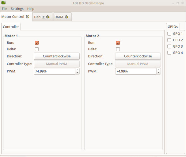
This dialog allows manual control of the two motors by directly specifying the fill factor of the PWM signals applied to control the 3-phase inverters. The motors are driven using a 6-step commutation algorithm.
Control |
Description |
|---|---|
Run |
Starts the motor |
Delta |
Selects between Star-like and Delta commutation sequence |
Direction |
Selects between clockwise and counterclockwise rotation |
PWM |
In Manual mode, settable between 50%–100% |
QDESYS Motor Control IP
QDESYS provides the following reference designs for the AD-FMCMOTCON2-EBZ:
EtherCAT design showing how to perform real-time motor control over the network
A high-performance Field Oriented Controller (FOC) - the FOC algorithm is provided as a highly optimized IP that can be integrated into the FPGA project
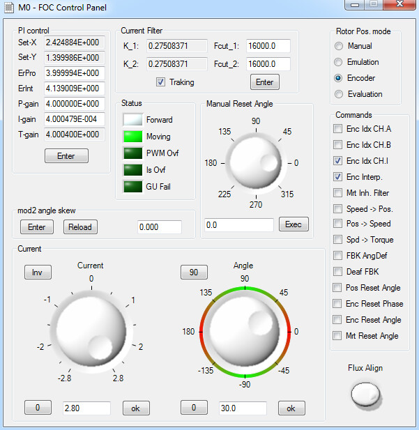
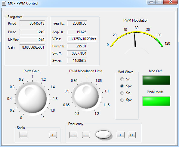
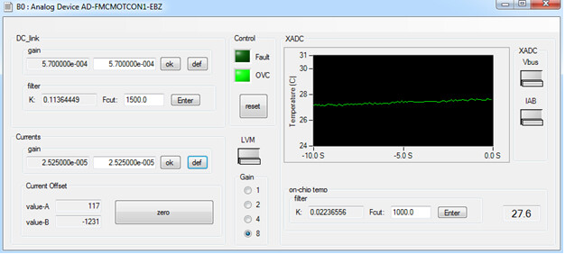
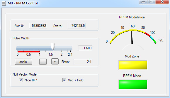
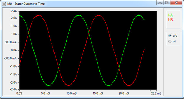
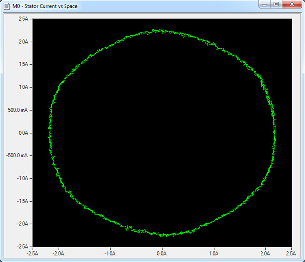
Screenshots from the user application taken while running with the AD-FMCMOTCON2-EBZ: