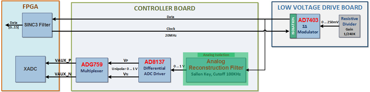
AD-FMCMOTCON2-EBZ Signal Measurement Chain
The motor control system measures the Ia (phase A current), Ib (phase B current), and Vbus using signal chains that span both the controller and low voltage driver boards. The entire analog front end is on the drive board; only digital signals are exchanged between the controller and drive boards.
Ia, Ib Measurement Signal Chain
The Ia and Ib currents are sensed using 10 mΩ shunt resistors. The ADC is placed in the proximity of the shunt resistor to reduce noise coupling. The small differential voltage on the shunt resistor is measured directly with the AD7403 isolated ΣΔ modulator without the need for extra interfacing and signal conditioning circuitry. The digital data and clock signals travel the entire length of the drive and controller boards all the way to the FPGA. Since the analog signals are digitized close to the source and sent in digital format to the FPGA, there are no concerns related to measurement quality.
The Ia and Ib XADC measurement chain utilizes the entire path of the regular measurement chain and adds a Sallen Key analog reconstruction filter after the AD7403 isolated ΣΔ modulator on the controller board, implemented using AD8646 operational amplifiers. The combination of the isolated ΣΔ modulator and the analog reconstruction filter provides a convenient and cost-effective way to achieve analog isolation of the XADC input signals. This analog isolation technique is described in CN0185.
The equation for calculating Ia or Ib is:
\(I = (ADCvalue - 2^{ADCbits-1}) \times ADCrange / 2^{ADCbits-1} \times R_{shunt}\)
where \(R_{shunt} = 10e{-3}\,\Omega,\; ADCrange = 320e{-3}\,V,\; ADCbits = 16\)

Vbus Measurement Signal Chain
Vbus sensing is done on the drive board using a resistive divider and the AD7403 ΣΔ modulator. The Vbus XADC measurement chain utilizes the entire path of the regular measurement chain and adds a Sallen Key analog reconstruction filter after the AD7403 isolated ΣΔ modulator on the controller board, implemented using AD8646 operational amplifiers.
The equation for calculating Vbus is:
\(V = (ADCvalue-2^{ADCbits-1}) \times ADCrange / 2^{ADCbits-1} \times gain\)
where \(ADCrange = 320e{-3}\,V,\; ADCbits = 16,\; gain = \frac{1}{220.1}\)