AD-DRVLV2-EBZ Low Voltage Drive Board
Features
Connects to the Controller board with a power stage that drives motors up to 48 V and 20 A
Drives 2 motors simultaneously
High frequency drive stage implemented with ADI isolated gate drivers
Supported motor types
BLDC
PMSM
Brushed DC
Stepper (bipolar / unipolar)
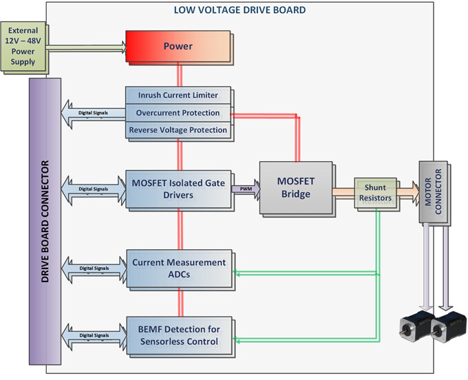
Integrated over current protection
Reverse voltage protection
Current and voltage measurement using isolated ADCs
Current measurement on 2 phases for 2 motors
DC Link Voltage measurement
BEMF zero cross detection for sensorless control of PMSM or BLDC motors
Separate voltage supplies for the 2 motors so that the motors do not influence each other
Block Diagram
Picture and Main Components
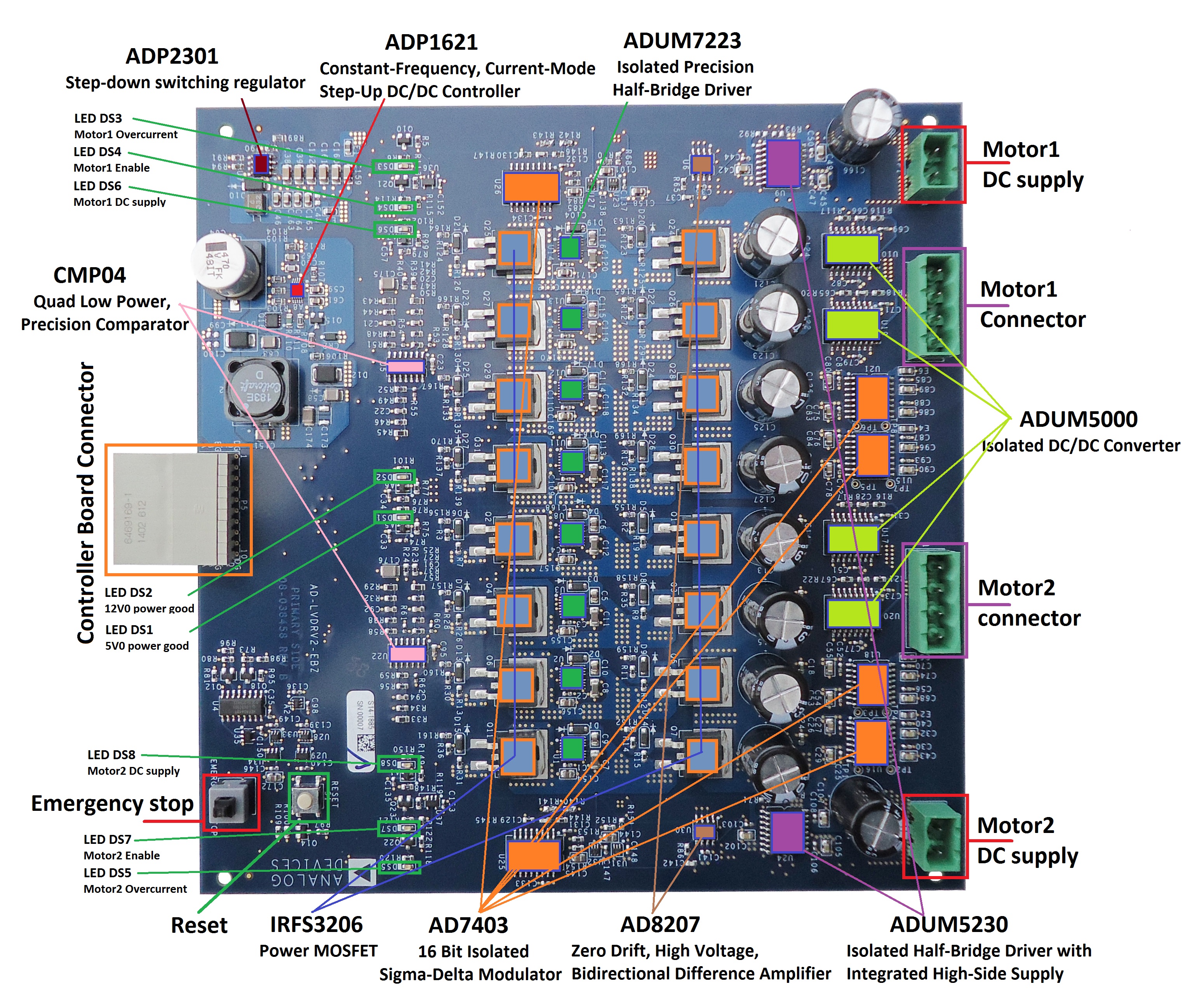
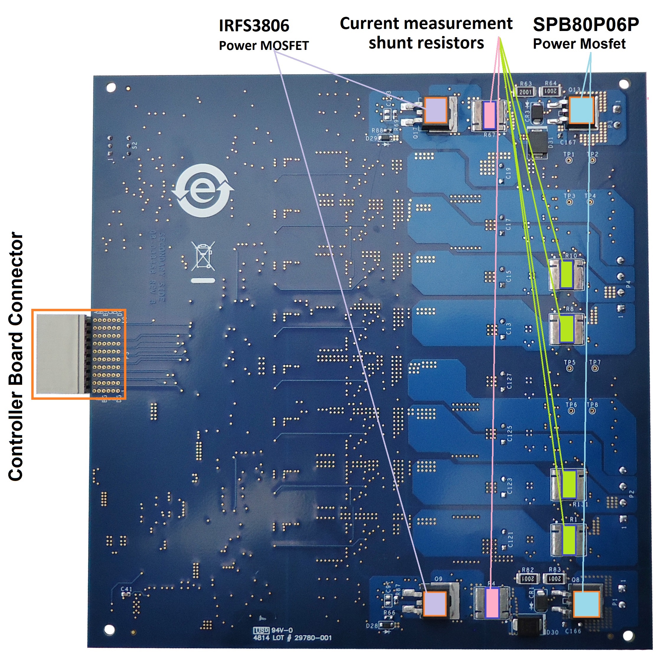
Key Parts
Part |
Description |
|---|---|
Measurement |
|
16-bit isolated 2nd order Sigma-Delta modulator |
|
Zero drift, high voltage, bidirectional difference amplifier |
|
Quad low power, precision comparator |
|
Power |
|
isoPower® integrated isolated dc-to-dc converter |
|
Constant-frequency, current-mode step-up dc/dc controller |
|
1.2 A, 20 V, 1.4 MHz non-synchronous step-down switching regulator |
|
MOSFET Drivers |
|
Isolated half-bridge driver with integrated high-side supply |
|
Isolated precision half-bridge driver, 4.0 A output |
Switches
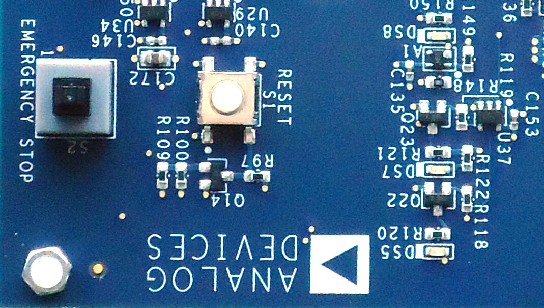
Emergency Stop switch
S2 is a latching emergency stop switch.
If triggered, the supply for the power stage is turned off.
Reset switch
S1 is a reset switch for the emergency stop latch.
Pressing S1 when S2 is not pressed turns the power stage on.