AD-FMCMOTCON2-EBZ Test Procedure
Required hardware
ZedBoard with mouse and keyboard
SD card with ADI Linux image
HDMI monitor
AD-FMCMOTCON2-EBZ
AD-DYNO2-EBZ
Prepare the SD card
Note
Following instructions are valid if a Windows host is used. Instructions regarding other operating systems can be found in the Kuiper Linux documentation.
Flash the Kuiper Linux SD card image following the Kuiper Linux documentation.
On Windows, use Win32DiskImager: select the image file, select the SD card device, and press Write.
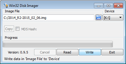
Use Windows “Safely Remove” to eject the disk.
Program the FRU EEPROM
Connect the controller board to the ZedBoard
Ensure that the SD card is up to date (run ADI Update Tools)
To program the FRU EEPROM, start ADI IIO Oscilloscope, select Settings -> Connect; if the EEPROM memory was not already programmed, a window should appear:
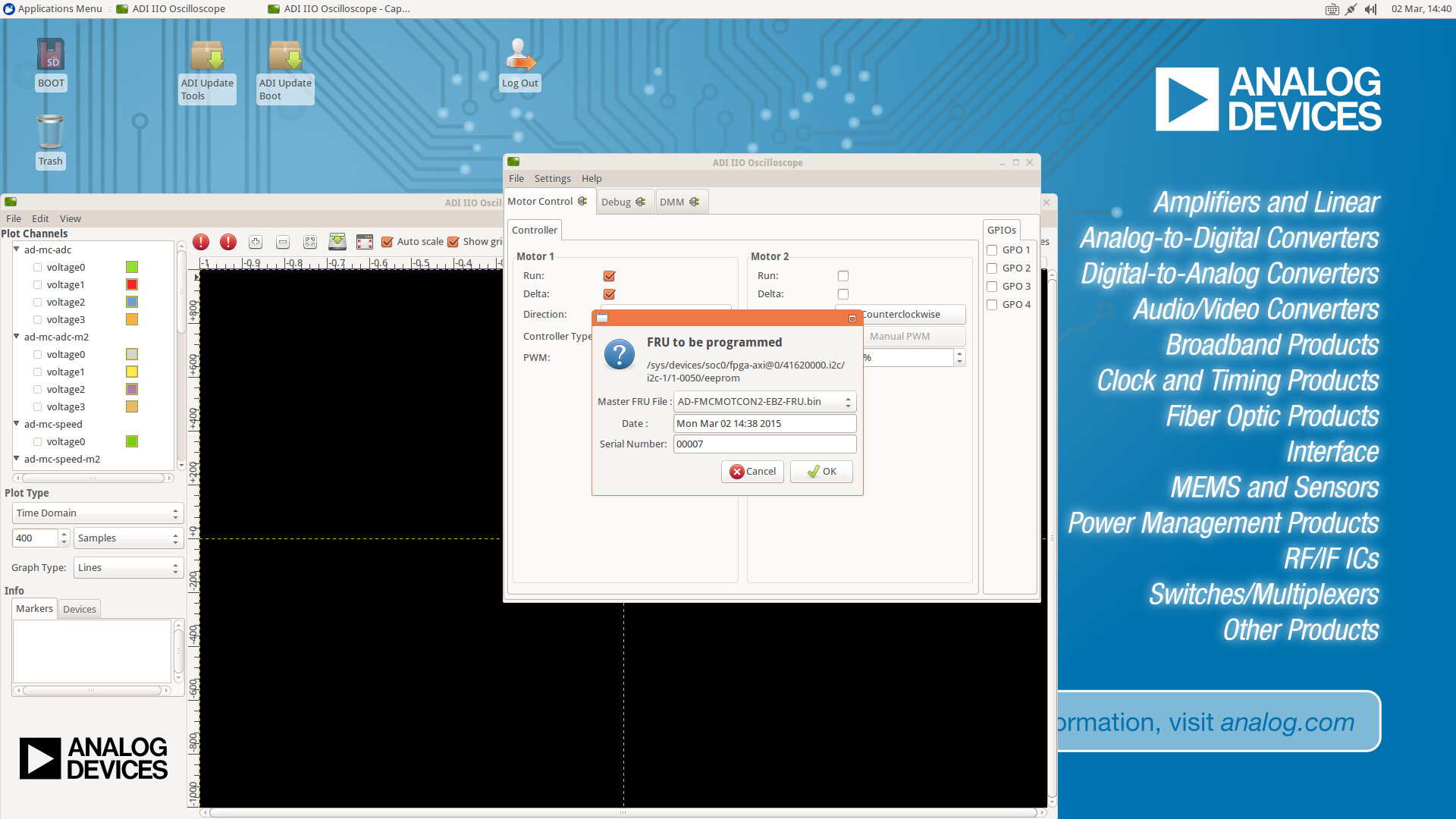
Select the AD-FMCMOTCON2-EBZ-FRU.bin master file, type the board’s Serial Number (written on the sticker on the controller board bottom), the Date, and click OK to program the EEPROM.
Test EtherCAT EEPROM
Open a Terminal Emulator and test the EEPROM memory by running
sudo ./verify_eepromIf everything works correctly, the following messages should appear: “Write OK.” “Read OK.”
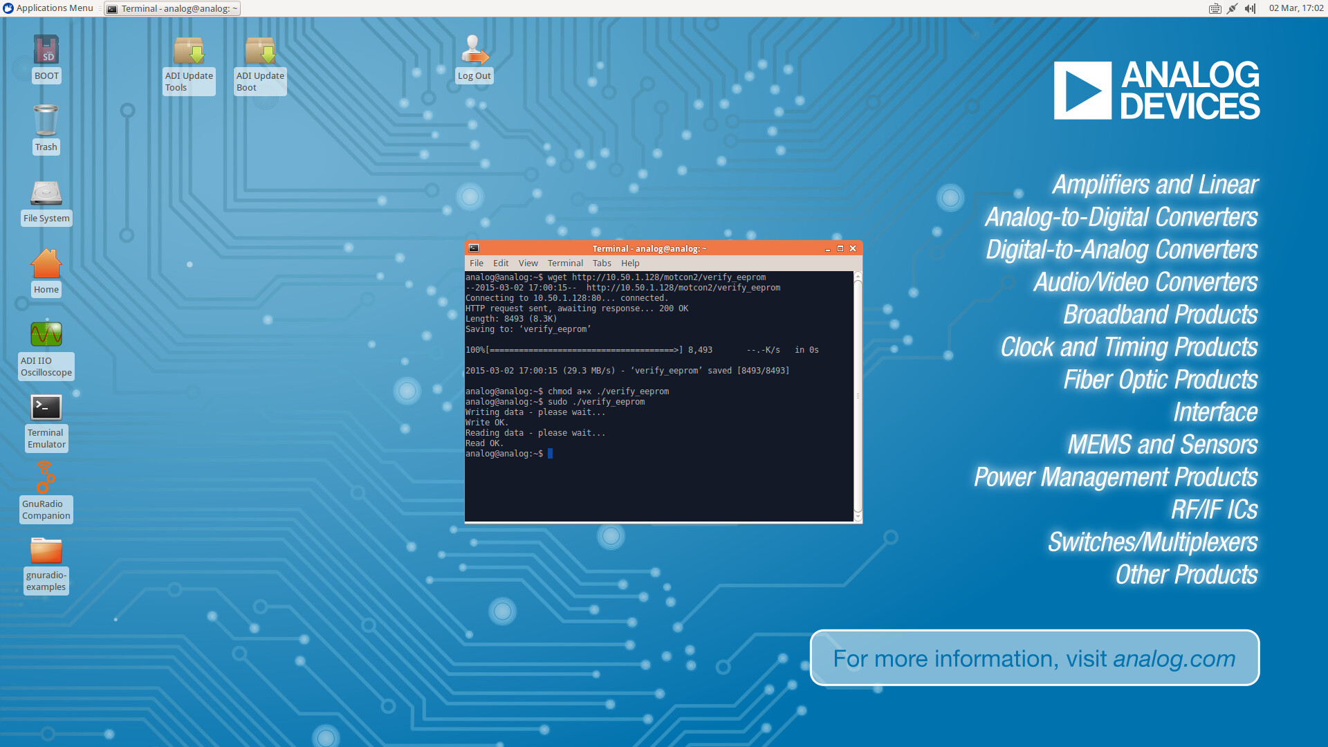
Test AD2S1210
Ensure that the SD card is up to date (run ADI Update Tools and
sudo adi_update_boot.sh 10.50.1.128)Connect a jumper on P6.2–P6.3
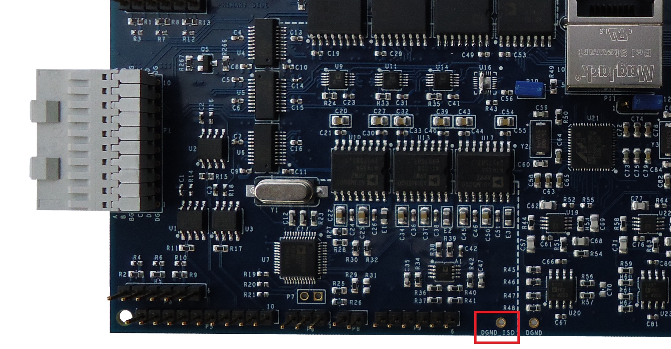
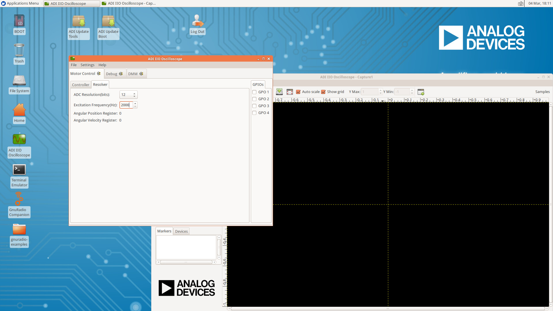
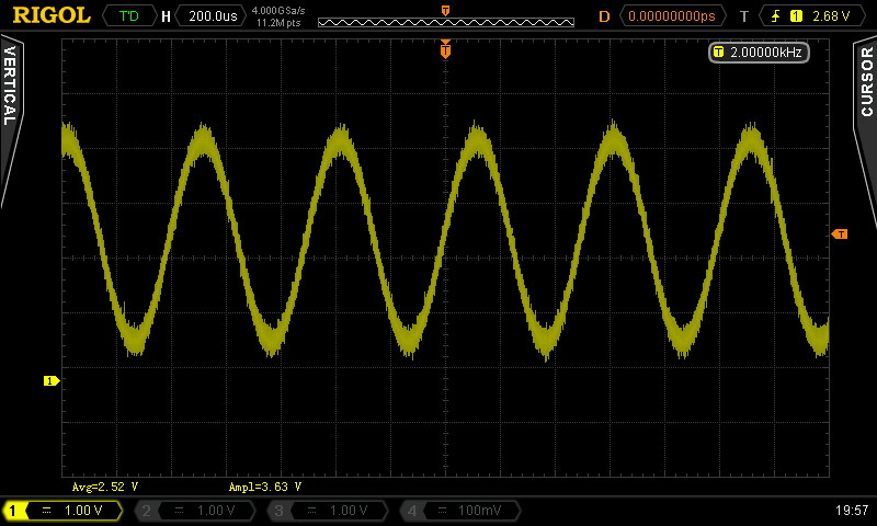
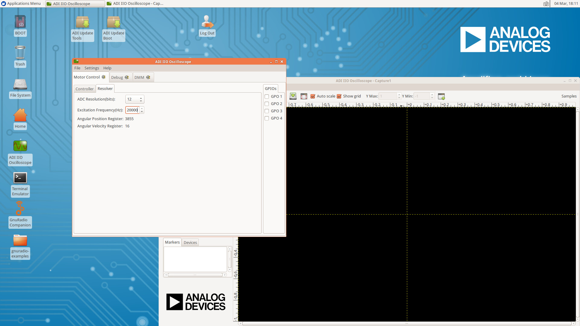
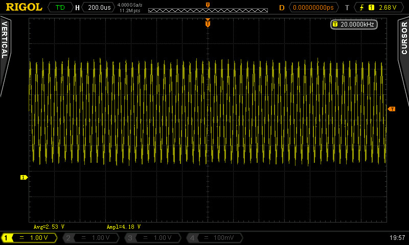
From the Resolver tab set the Excitation Frequency to 2000 Hz and 20000 Hz. Measure the Sine frequency on P9.5 using an oscilloscope. Ensure the oscilloscope ground is connected to the DGND_ISO testpoint.
Test Procedure
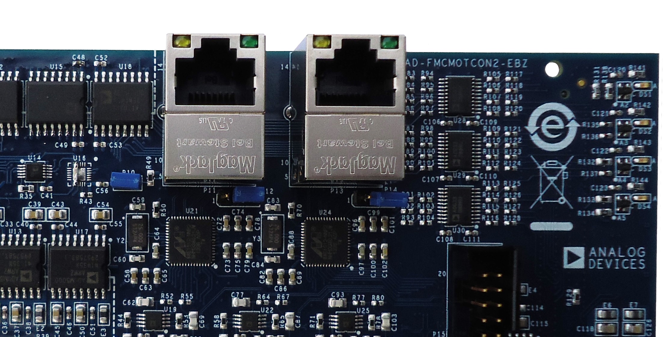
Insert three jumpers on the controller board as shown below:
Connect the hardware as shown below:
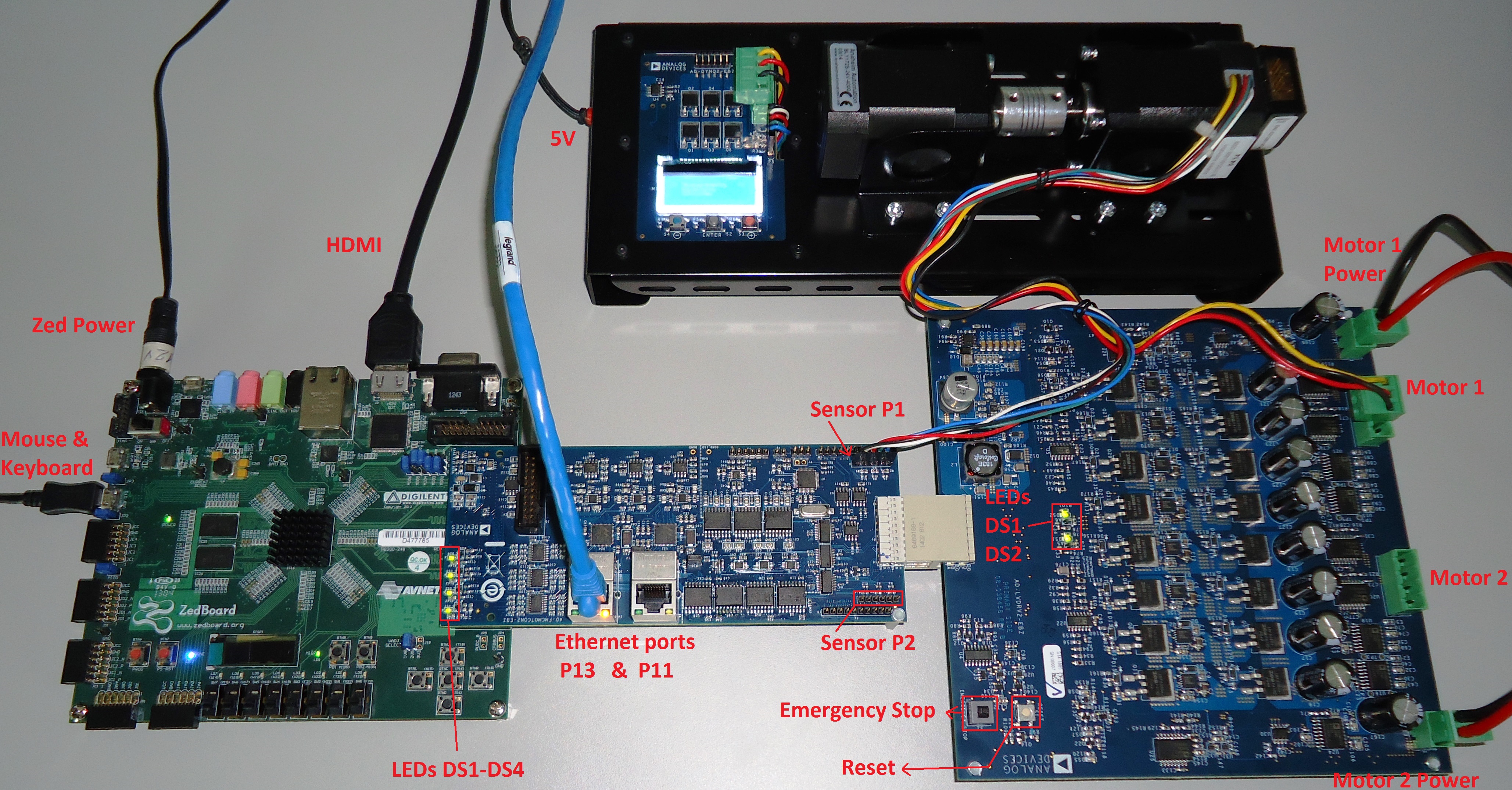
Insert the Dyno sensor wire in P3 connector on the controller board with the black wire towards the FPGA
Insert the Dyno motor wire in the P2 connector on the Drive Board
Connect 24 V power supplies on P1 and P3 connectors
Make sure the Emergency Stop switch is pressed
Power on the ZedBoard
Make sure the following LEDs are on:
DS1, DS2, DS3 and DS4 on the Controller Board
DS1 and DS2 on the Drive Board
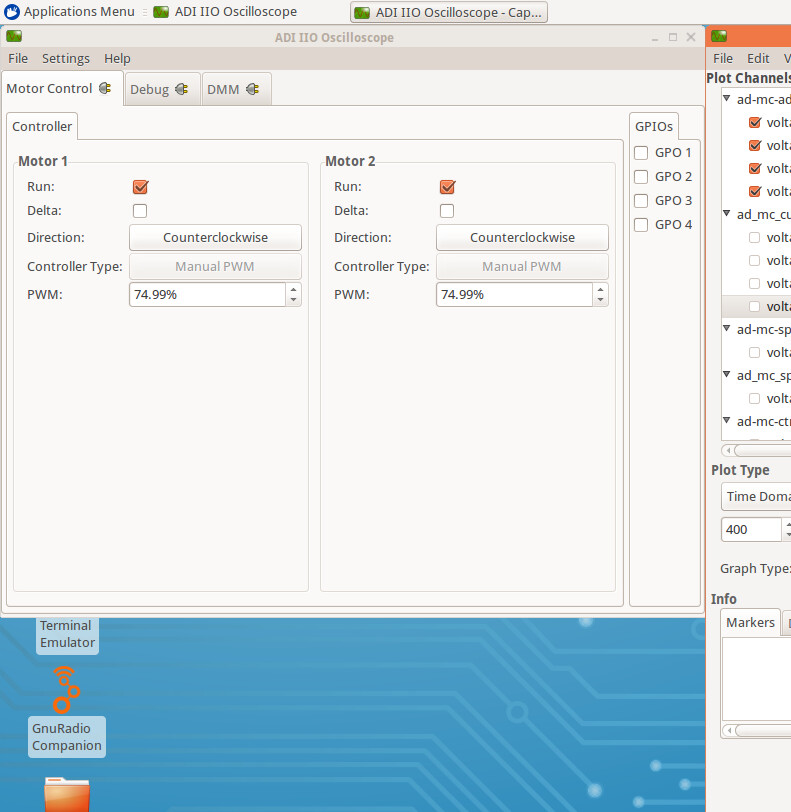
In the Linux ADI IIO Oscilloscope go to the Motor Control tab and select the following configuration:
Motor 1
Run: ON
Delta: OFF
Direction: Counterclockwise
PWM: 74.99%
Motor 2
Run: ON
Delta: OFF
Direction: Counterclockwise
PWM: 74.99%
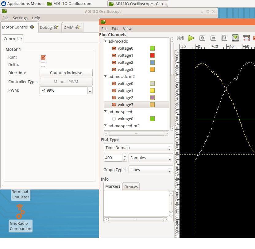
In the Linux ADI IIO Oscilloscope–Capture1 go to the Plot Channels pane and select the following configuration:
ad-mc-adc: voltage0–voltage3 ON
ad-mc-adc-m2: voltage0–voltage3 ON
ADC
Release the Emergency Stop switch and press the Reset switch - the motor should start spinning
Make sure that there are no vibrations in the DYNO system
In the Linux ADI IIO Oscilloscope–Capture1 press Capture, AutoZoom, and Stop
Press the Emergency Stop switch - the motor should stop spinning
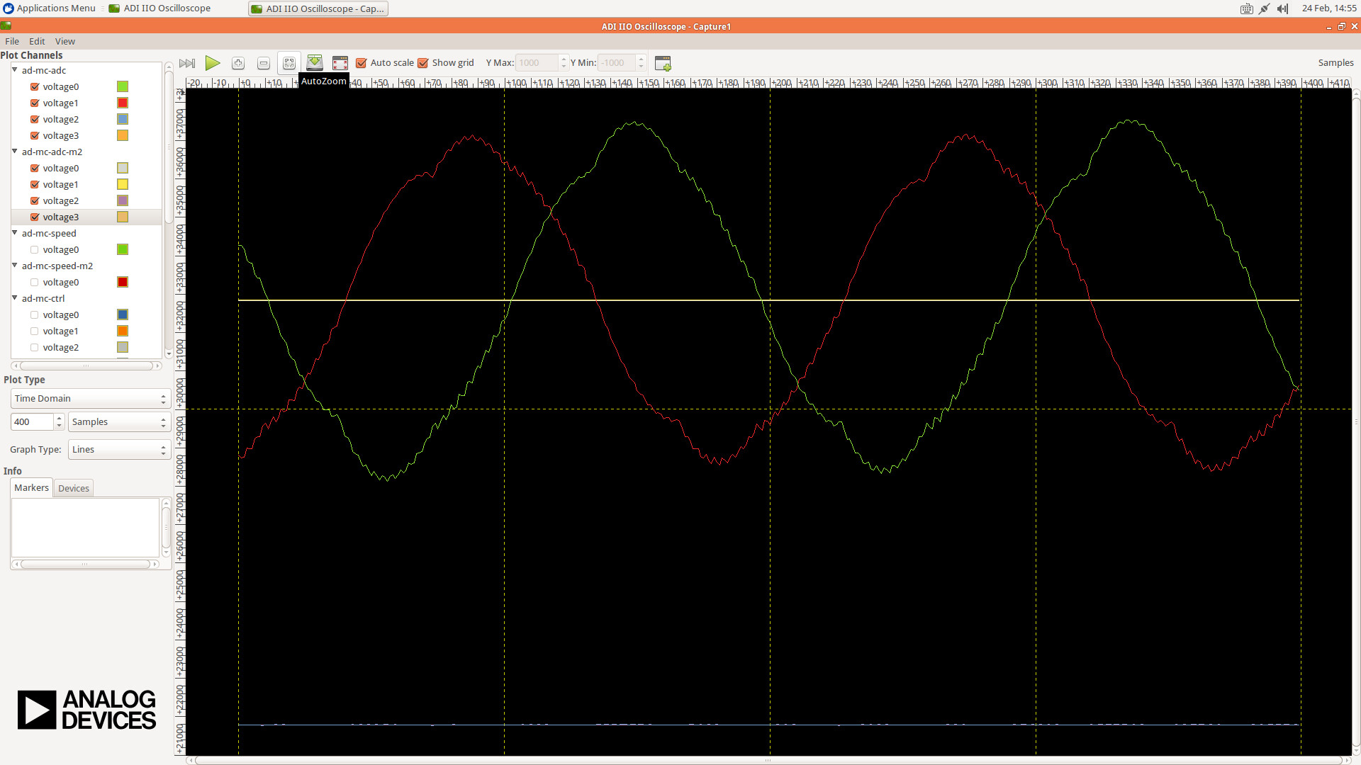
Make sure there are two phase-shifted sinusoidal waveforms on screen with amplitude between 27000 and 37000
Make sure there is a DC signal at approximately 21500
Insert the Dyno sensor wire in P2 connector on the controller board with the black wire towards the FPGA
Insert the Dyno motor wire in the P4 connector on the Drive Board
Release the Emergency Stop switch and press the Reset switch - the motor should start spinning
Make sure that there are no vibrations in the DYNO system
In the Linux ADI IIO Oscilloscope–Capture1 press Capture, AutoZoom, and Stop
Press the Emergency Stop switch - the motor should stop spinning
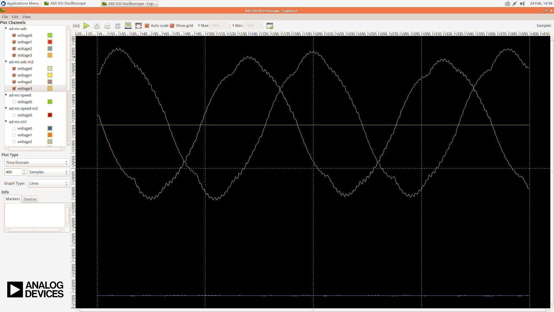
Make sure there are two phase-shifted sinusoidal waveforms on screen with amplitude between 27000 and 37000
Make sure there is a DC signal at approximately 21500
Ethernet
Insert an Ethernet cable in the P13 connector on the controller board
Install Iperf on a Windows machine
Find the IP address of the ZedBoard by running
ifconfigin a terminalRun Iperf server on the ZedBoard:
iperf -sRun Iperf client on the Windows PC, replacing x.x.x.x with the ZedBoard IP:
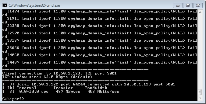
iperf -c x.x.x.xAfter a few seconds a result should appear. For a Gigabit Ethernet connection, ensure the speed is greater than 150 Mbit/s.
Insert the Ethernet cable in the P11 connector on the controller board and repeat the steps above.
Dyno
Release the Emergency Stop switch and press the Reset switch - the motor should start spinning
Make sure that there are no vibrations in the DYNO system
On the DYNO board open the Measurements menu
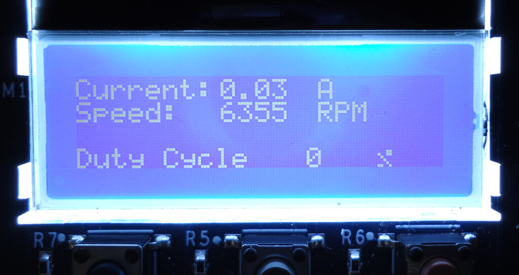
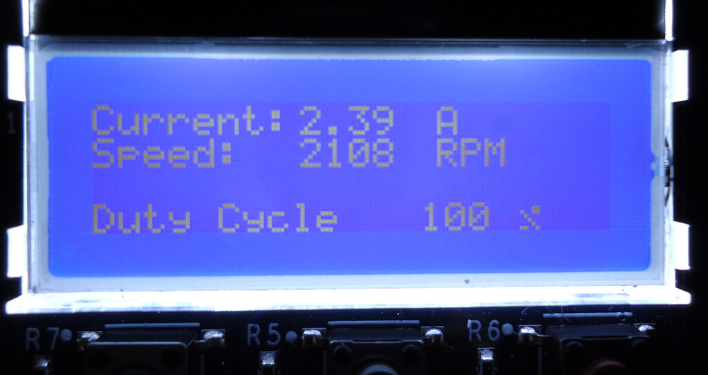
Check the speed and current displayed under Measurements on the DYNO LCD: 6300 rpm ±250 rpm for speed and 0.03 A for current
Set the load to 100%
Check the speed and current: 2100 rpm ±250 rpm for speed and 2.4 A ±0.1 A for current
Press the Emergency Stop switch - the motor should stop spinning