Quick start
The Quick Start Guides provide step-by-step instructions on how to do an initial system setup for the AD-FMCMOTCON2-EBZ on an FPGA development board.
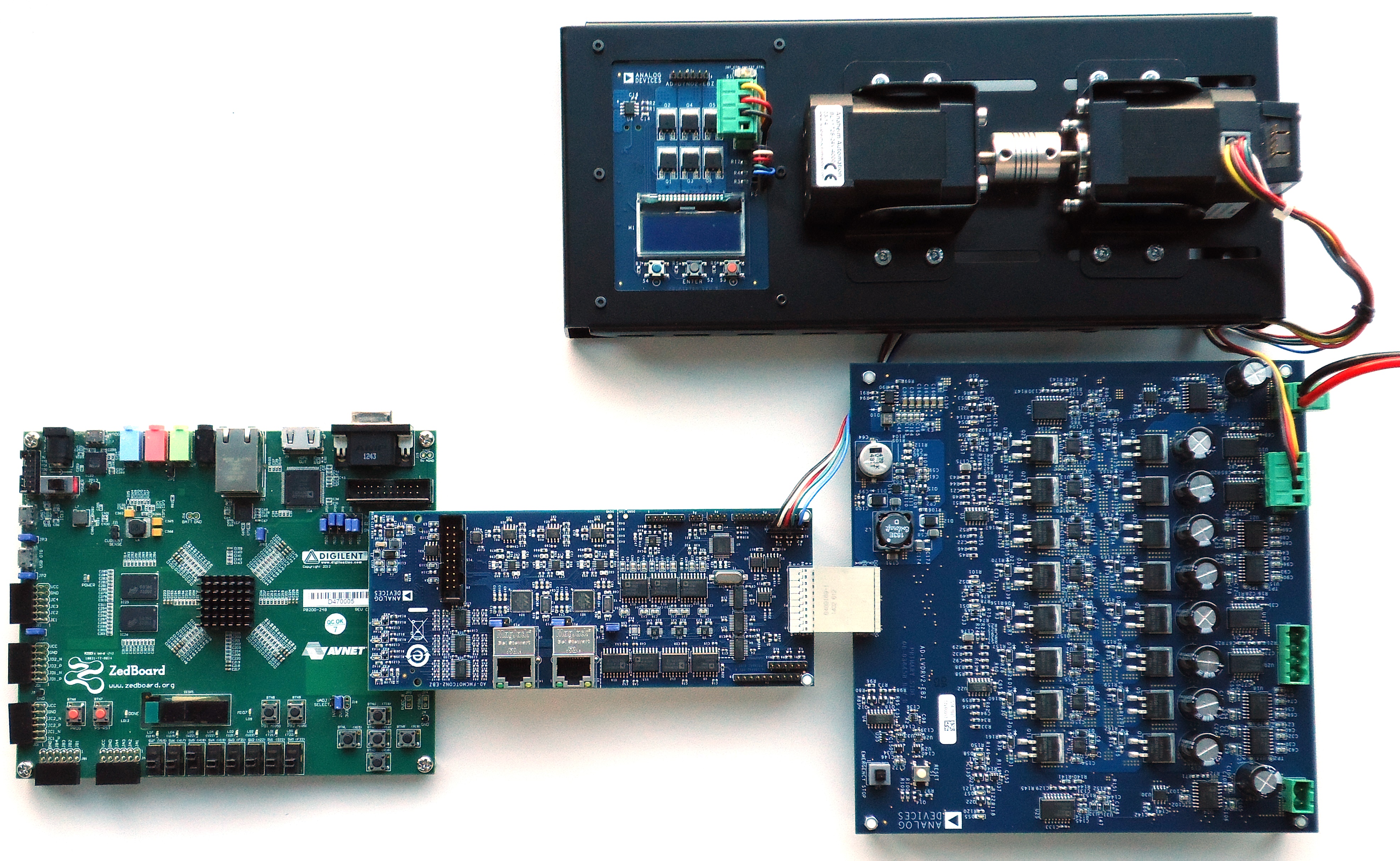
Supported carriers
The AD-FMCMOTCON2-EBZ board connects to the FMC LPC connector on the carrier.
Board |
AD-FMCMOTCON2-EBZ |
|---|---|
FMC LPC |
Supported environments
Board |
HDL |
Linux |
No-OS |
|---|---|---|---|
Yes (Vivado) |
Yes |
No |
Hardware setup
Connect the hardware as shown in the picture below:
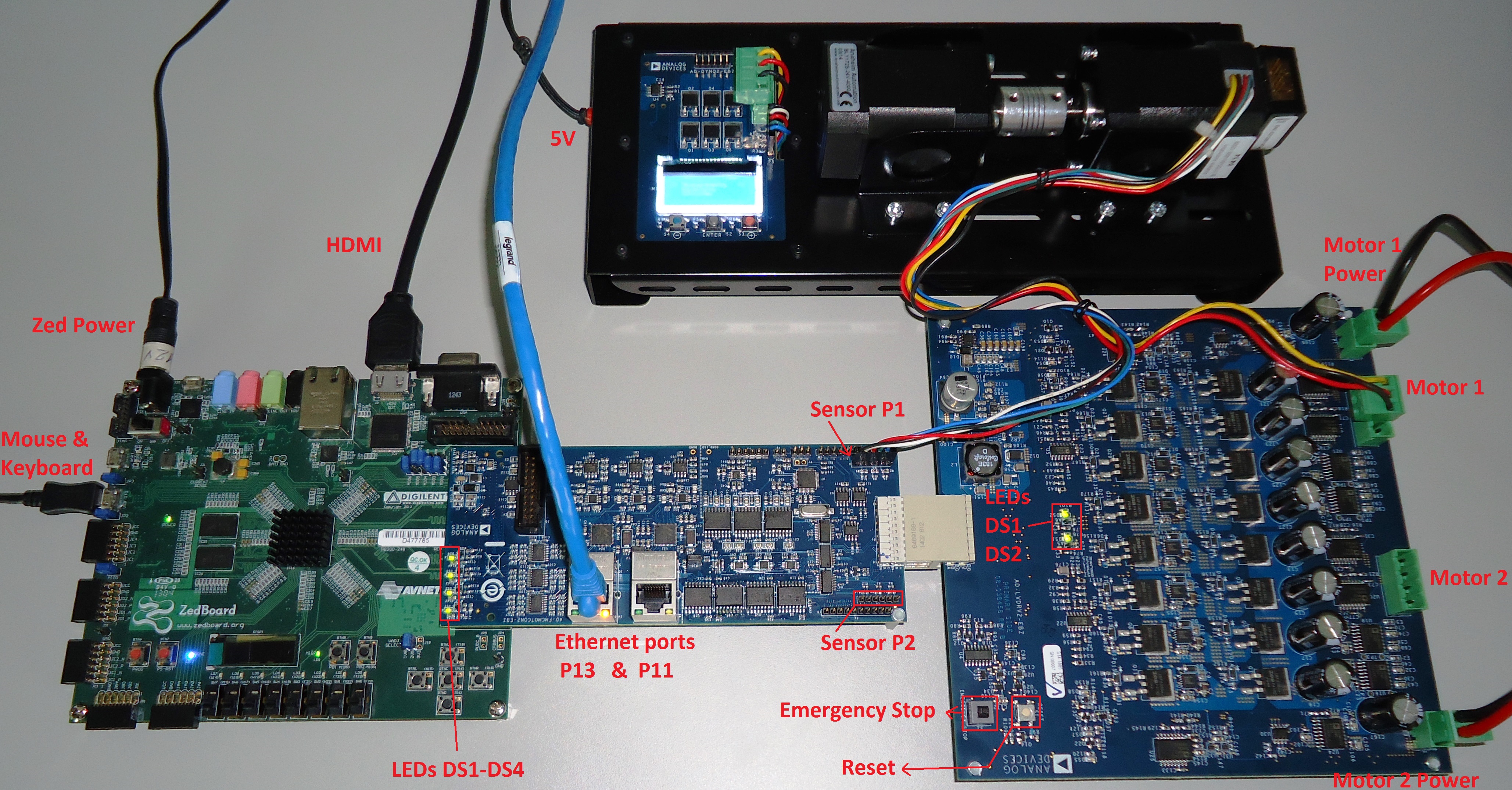
Make sure the Emergency Stop switch is pressed (see the LV Board description for more information about the drive board buttons)
Insert the DYNO sensor wire in the P3 connector on the controller board with the black wire towards the ZedBoard. If using an encoder, there is a one-to-one correspondence between the encoder pins and the P3 connector pins.
Insert the DYNO motor wire in the P2 connector on the Drive Board
Connect the power supply to the P1 connector and, if a second motor is used, also to the P3 connector
Make sure the following LEDs are ON:
DS1, DS2, DS3, and DS4 on the Controller Board
DS1 and DS2 on the Drive Board
Insert the 5 V supply in the left side of the DYNO
Power on the ZedBoard
After the ZedBoard is programmed, to start the motor, release the Emergency Stop switch and press the Reset switch for a few seconds