ZedBoard Quickstart
This guide provides quick instructions on how to set up the EVAL-ADAQ7980-SDZ on:
ZedBoard FMC LPC
All the products described on this page include ESD (electrostatic discharge) sensitive devices. Electrostatic charges as high as 4000V readily accumulate on the human body or test equipment and can discharge without detection. Although the boards feature ESD protection circuitry, permanent damage may occur on devices subjected to high-energy electrostatic discharges. Therefore, proper ESD precautions are recommended to avoid performance degradation or loss of functionality. This includes removing static charge on external equipment, cables, or antennas before connecting to the device.
Using no-OS as software
Necessary files
Note
The no-OS setup boots from an SD card containing the boot image. The following files must be built before running the system.
The following file is needed for the system to boot:
Boot image:
BOOT.BIN
The boot image contains the FPGA bitstream and no-OS application, and must be built manually from source:
Instructions on how to build the HDL bitstream can be found here: HDL User Guide with ADAQ7980 HDL project. More details at Build an HDL project.
Instructions on how to build the no-OS software can be found here: No-OS Build Guide with ADAQ7980 no-OS project.
Instructions on how to create the BOOT.BIN file: Build the boot image BOOT.BIN
Required Software
AMD Xilinx Vivado Design Suite (for HDL build and creating BOOT.BIN)
ARM GNU Toolchain (for no-OS build)
A UART terminal (PuTTY/Tera Term/Minicom, etc.) with baud rate 115200 (8N1)
SD card formatting tool (SD Card Formatter, balenaEtcher, or dd on Linux)
Git
Required Hardware
AMD Xilinx ZedBoard FPGA development board and its power supply (12V/3A)
EVAL-ADAQ7980-SDZ evaluation board
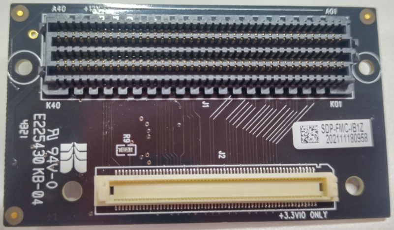
EVAL-SDP-CK1Z FMC-I-SDP interposer board (required to connect SDP board to FMC connector)
SD card with at least 512MB of memory (formatted as FAT32)
SMA cable to connect to the signal source
Micro-USB cable (for UART communication)
Function generator or signal source
More details as to why you need these can be found at Prerequisites.
Testing
Creating the setup
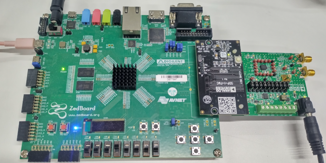
The setup is connecting the EVAL-ADAQ7980-SDZ to the ZedBoard via the FMC-I-SDP interposer.
Important
The EVAL-ADAQ7980-SDZ uses the SDP (Serial Device Port) format connector, which is not directly compatible with the ZedBoard’s FMC connector. The FMC-I-SDP interposer board is required to bridge between these two connector types.
Follow the steps in this order, to avoid damaging the components:
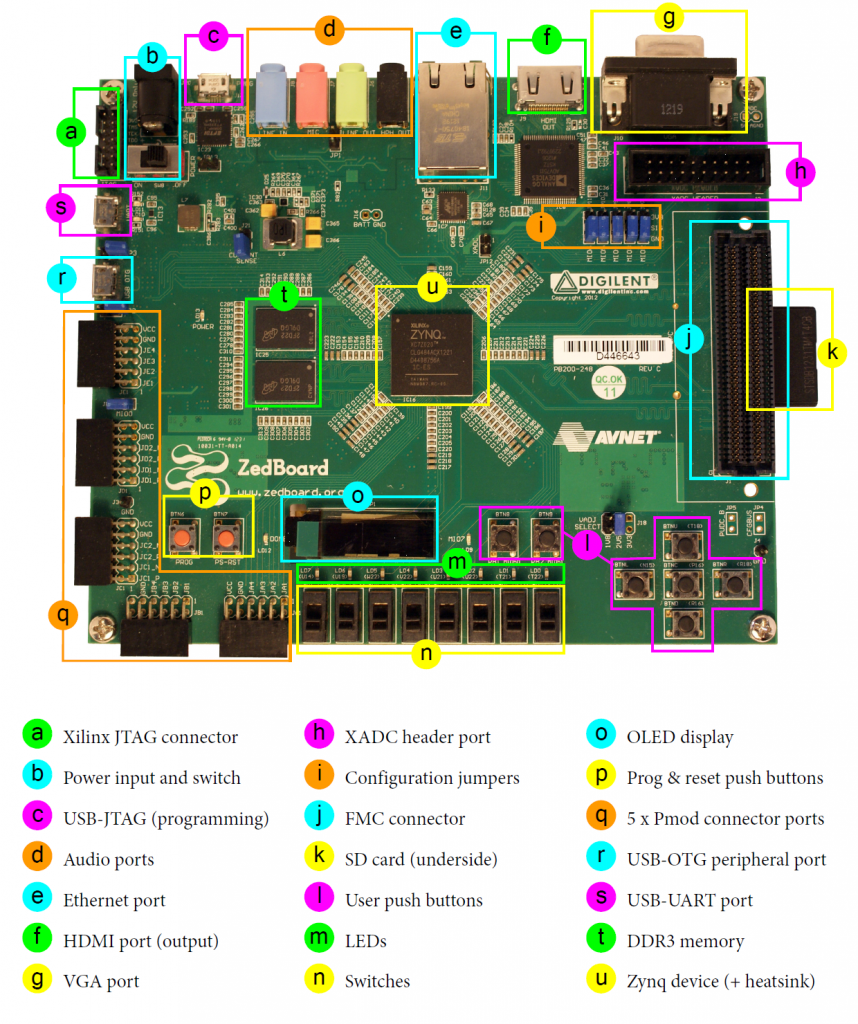
Get the ZedBoard
Prepare the SD card:
Format the SD card as FAT32
Copy the
BOOT.BINfile to the root directory of the SD cardSafely eject the SD card from your computer
Configure ZedBoard for SD card boot mode:
The BOOT mode jumpers (JP7-JP11) must be set for SD card boot mode as follows:
Table 1 Boot Mode Jumper Settings Jumper
Position
MIO6 (JP7)
GND
MIO5 (JP8)
GND
MIO4 (JP9)
3V3
MIO3 (JP10)
3V3
MIO2 (JP11)
GND
Note
SD card boot mode loads the boot image automatically from the SD card on power-up, eliminating the need for JTAG programming tools.
Install the FMC-I-SDP interposer board:
Align the FMC-I-SDP interposer with the ZedBoard’s FMC LPC connector (J21)
Press firmly until fully seated
The interposer should sit flat against the ZedBoard
Connect the EVAL-ADAQ7980-SDZ to the FMC-I-SDP:
Align the EVAL-ADAQ7980-SDZ’s SDP connector with the interposer’s SDP socket
Press firmly until fully seated
Ensure the connection is secure
Connect the signal source:
Connect your signal source to the SMA connector (J1) on the EVAL-ADAQ7980-SDZ using an SMA cable
Alternatively, use the screw terminals if your sensor doesn’t have an SMA output
Do not enable the signal source output yet
Connect the micro-USB cable:
Connect the micro-USB cable from the ZedBoard’s USB-UART port (J14) to your PC
This provides both UART communication and JTAG programming interface
Note
On Windows, if drivers don’t install automatically, download the Xilinx Cable Drivers.
Insert the SD card:
Insert the prepared SD card into the ZedBoard’s SD card slot (J12)
Ensure the card is fully inserted and clicks into place
Connect power:
Plug the 12V power supply into the ZedBoard’s power input connector (J20)
DO NOT turn on the power switch yet
Verify all connections:
☐ FMC-I-SDP interposer connected to ZedBoard FMC connector
☐ EVAL-ADAQ7980-SDZ connected to FMC-I-SDP interposer
☐ Signal source connected to SMA input (output disabled)
☐ USB cable connected to USB-UART port
☐ SD card inserted with BOOT.BIN file
☐ Boot mode jumpers set to SD card mode (MIO[5:2]=0110)
☐ Power supply connected (power switch OFF)
Power on the system:
Turn on the power switch (SW8) on the ZedBoard
A green LED (LD13, POWER) lights up immediately
The system will automatically boot from the SD card
A blue LED (LD12, DONE) will light up once the FPGA is programmed
The no-OS application will start automatically
Booting and running
After the hardware is connected and powered on, the system will boot automatically from the SD card.
Open a serial terminal and connect to the ZedBoard:
Baud rate: 115200
Data bits: 8
Parity: None
Stop bits: 1
Flow control: None
# Linux example
screen /dev/ttyUSB0 115200

# Windows: Use PuTTY or Tera Term
# Find COM port in Device Manager under "Ports (COM & LPT)"
Observe the boot sequence:
The ZedBoard will automatically:
Load the First Stage Boot Loader (FSBL) from BOOT.BIN
Program the FPGA with the bitstream
Load and execute the no-OS application
Start outputting data to the serial console
This process takes approximately 3-5 seconds after power-on.
Enable the signal source:
Configure your function generator:
Signal type: Sine wave
Frequency: 1 kHz
Amplitude: 2 Vpp
DC Offset: 0 V
Output Load: High Z (Hi-Z)
Toggle the function generator’s output to ON
Console output
The following is what is printed in the serial console after the system boots:
ADAQ7980 no-OS Driver Example
==============================

Initializing ADAQ7980...
SPI Engine: Configuring...
SPI Engine: Data width: 16 bits
SPI Engine: Max speed: 10 MHz
SPI Engine: Mode: 0 (CPOL=0, CPHA=0)
SPI Engine: Initialized successfully

ADAQ7980: Configuring...
ADAQ7980: Chip ID: 0x0DA0
ADAQ7980: Turbo mode: ENABLED
ADAQ7980: Output coding: Twos complement
ADAQ7980: Span compression: DISABLED
ADAQ7980: High-Z mode: DISABLED
ADAQ7980: Initialized successfully

Starting continuous conversion...
Press any key to stop acquisition

Sample    0: 0x8000 ( 0.000 V)
Sample   10: 0x8123 ( 0.035 V)
Sample   20: 0x8456 ( 0.134 V)
Sample   30: 0x8892 ( 0.268 V)
Sample   40: 0x8D45 ( 0.413 V)
Sample   50: 0x9234 ( 0.568 V)
Sample   60: 0x9723 ( 0.724 V)
Sample   70: 0x9C12 ( 0.879 V)
Sample   80: 0xA045 ( 1.005 V)
Sample   90: 0xA3F2 ( 1.124 V)
Sample  100: 0xA6D8 ( 1.214 V)
Sample  110: 0xA8BC ( 1.273 V)
Sample  120: 0xA9F4 ( 1.304 V)
Sample  130: 0xAA3E ( 1.315 V)
Sample  140: 0xA9D2 ( 1.301 V)
Sample  150: 0xA8A1 ( 1.268 V)
Sample  160: 0xA6C3 ( 1.211 V)
Sample  170: 0xA3D4 ( 1.119 V)
Sample  180: 0xA012 ( 0.996 V)
Sample  190: 0x9BE2 ( 0.873 V)
Sample  200: 0x96F3 ( 0.718 V)
Sample  210: 0x9201 ( 0.563 V)
Sample  220: 0x8D12 ( 0.408 V)
Sample  230: 0x8865 ( 0.262 V)
Sample  240: 0x8423 ( 0.129 V)
Sample  250: 0x80F1 ( 0.029 V)
Sample  260: 0x7FFF (-0.000 V)
Sample  270: 0x7EDC (-0.035 V)
Sample  280: 0x7BA9 (-0.134 V)
Sample  290: 0x776D (-0.268 V)
Sample  300: 0x72BA (-0.413 V)
Sample  310: 0x6DCB (-0.568 V)
Sample  320: 0x68DC (-0.724 V)
Sample  330: 0x63ED (-0.879 V)
Sample  340: 0x5FBA (-1.005 V)
Sample  350: 0x5C0D (-1.124 V)
Sample  360: 0x5927 (-1.214 V)
Sample  370: 0x5743 (-1.273 V)
Sample  380: 0x560B (-1.304 V)
Sample  390: 0x55C1 (-1.315 V)
Sample  400: 0x562D (-1.301 V)
Sample  410: 0x575E (-1.268 V)
Sample  420: 0x593C (-1.211 V)
Sample  430: 0x5C2B (-1.119 V)
Sample  440: 0x5FED (-0.996 V)
Sample  450: 0x641D (-0.873 V)
Sample  460: 0x690C (-0.718 V)
Sample  470: 0x6DFE (-0.563 V)
Sample  480: 0x72ED (-0.408 V)
Sample  490: 0x779A (-0.262 V)
Sample  500: 0x7BDC (-0.129 V)
Sample  510: 0x7F0E (-0.029 V)

Acquisition stopped by user
Total samples captured: 512
The sample values will vary based on your input signal. The output shows:
Initialization messages confirming SPI Engine and ADAQ7980 configuration
Continuous ADC samples with both hexadecimal codes and voltage values
Sample values following the sine wave input (increasing, peak, decreasing, trough, repeat)
Useful commands and tips
Stopping acquisition: Press any key in the serial terminal to stop data acquisition.
Verifying operation:
With a DC input, readings should be stable near the input voltage
With a sine wave input, readings should smoothly transition between min and max
With input grounded (0V), readings should center around 0x8000 (mid-scale)
Modifying the application:
The no-OS application can be modified to:
Change data output format (hex, decimal, voltage)
Adjust sampling rate (configured in HDL)
Enable/disable turbo mode
Implement averaging or filtering
Export data to a file
See the ADAQ7980 no-OS project source for implementation details.
Troubleshooting
Problem: System does not boot (DONE LED does not light up)
Verify SD card is properly inserted and clicks into place
Check that BOOT.BIN file exists in the root directory of the SD card
Verify SD card is formatted as FAT32
Confirm boot mode jumpers are set correctly (MIO[5:2]=0110)
Try reformatting the SD card and copying BOOT.BIN again
Verify ZedBoard is powered on (green LED LD13 lit)
Problem: No serial output after power-on
Verify correct COM port is selected
Check baud rate is 115200 (8N1)
Ensure USB cable is connected to USB-UART port (J14)
Check that the DONE LED (LD12) is lit, indicating successful FPGA programming
Try power cycling the board (off, wait 5 seconds, on)
Problem: Incorrect ADC readings
Verify signal source is within ±10V input range
Check ground connection between signal source and board
Ensure signal source output is enabled
Verify proper impedance (use high-Z output on function generator)
Problem: Build errors
HDL: Verify Vivado version matches requirements
no-OS: Verify ARM toolchain is installed
no-OS: Ensure HARDWARE path points to HDL build output
BOOT.BIN: Verify bootgen is available in Vivado installation
Try clean rebuild:
make clean && make
Problem: SD card not recognized
Ensure SD card is 512MB or larger
Reformat as FAT32 (not exFAT or NTFS)
Try a different SD card (some older cards may not work)
Check SD card slot for debris or damage
Next steps
After successful setup:
Explore the ADAQ7980 driver API
Modify sampling rate in HDL:
projects/adaq7980_sdz/zed/system_bd.tclCustomize the application for your use case
Review HDL project documentation
Additional Resources
Hardware Documentation:
Software Documentation: