VCU118 Quick start
All the products described on this page include ESD (electrostatic discharge) sensitive devices. Electrostatic charges as high as 4000V readily accumulate on the human body or test equipment and can discharge without detection. Although the boards feature ESD protection circuitry, permanent damage may occur on devices subjected to high-energy electrostatic discharges. Therefore, proper ESD precautions are recommended to avoid performance degradation or loss of functionality. This includes removing static charge on external equipment, cables, or antennas before connecting to the device.
This guide provides quick instructions on how to set up the EVAL-AD9213 on:
VCU118 on the FMC+ connector
Using Linux as software
Necessary files
The following files are needed to program the system:
HDL bitstream:
system_top.bit, built from the Build an HDL projectLinux kernel image:
simpleImage.vcu118_ad9213_evb.strip, built from the Build MicroBlaze Linux kernelTCL script:
connect
fpga -f system_top.bit
after 1000
target 3
dow simpleImage.vcu118_ad9213_evb.strip
after 1000
con
disconnect
Gather all three files into a single working directory on the host PC before proceeding.
Note
Pre-built files for this reference design are not yet available. The files must be built manually using the links above. Official release artifacts will be provided here once available. You can also check the in-development Linux branch at 9213 branch and the HDL repository at ad9213_evb.
Required software
Xilinx
xsctorxsdb(included in Vivado/Vitis toolchain)A UART terminal (e.g. PuTTY/Tera Term/Minicom) at 115200 baud rate (8N1)
Required hardware
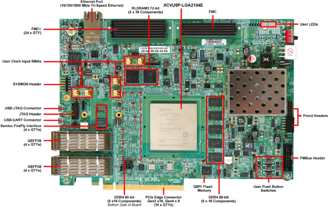
AMD Xilinx VCU118 FPGA board and its power supply
EVAL-AD9213 evaluation board
ZX180V-HSPC FMC VITA 57.4 Mezzanine card breakout adapter
2x Micro-USB cables (JTAG and UART)
More details as to why you need these can be found at Prerequisites.
Warning
The following modification is required before powering on the system:
The EVAL-AD9213 does not support JTAG boot in its default configuration. To enable it, insert the evaluation board into the ZX180V-HSPC FMC+ breakout adapter and solder a wire between pins D30 and D31 on the breakout adapter. This connection bridges the TDI and TDO lines, which is necessary to close the JTAG chain. See more details below.
Testing
Creating the setup
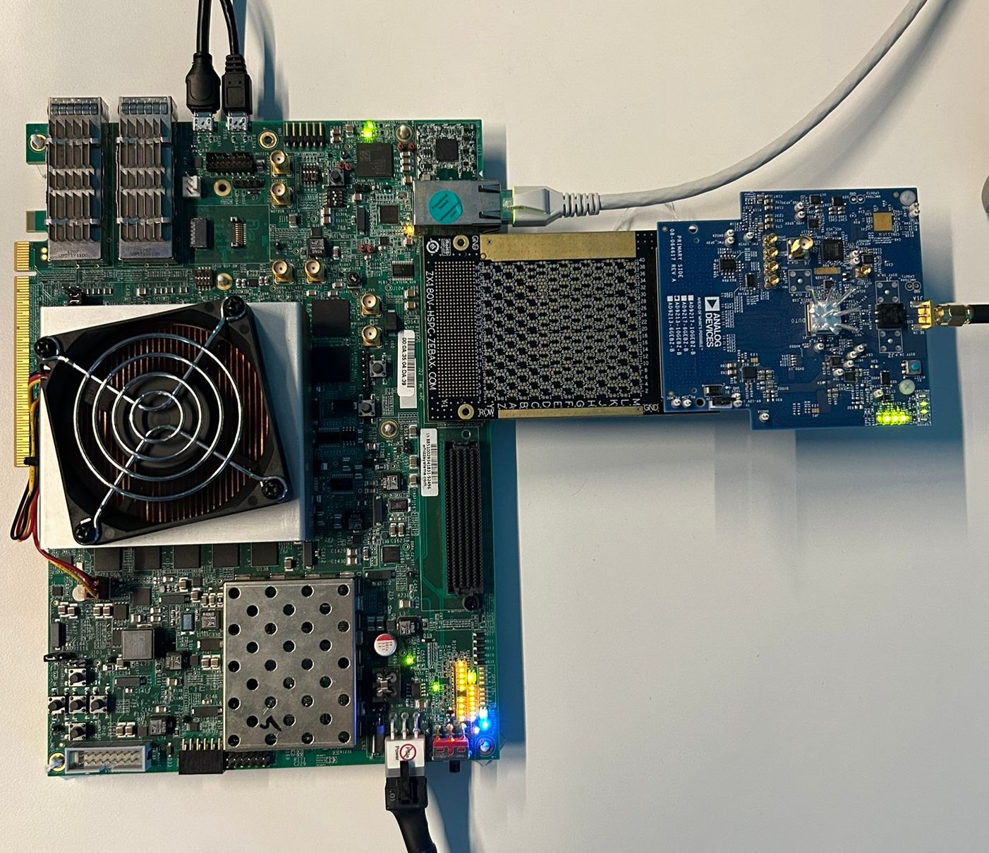
Follow the steps below in order to avoid damaging the components:
Solder a wire between pins D30 and D31 on the ZX180V-HSPC breakout adapter
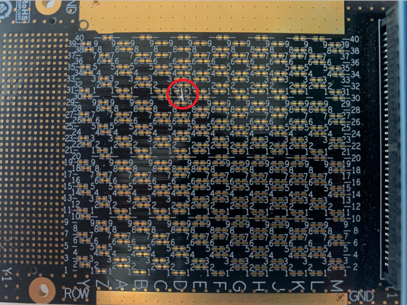
Figure 3 ZX180V-HSPC breakout adapter with TDI/TDO pins labeled
Insert the EVAL-AD9213 evaluation board into the ZX180V-HSPC FMC+ breakout adapter
Insert the FMC+ breakout adapter into the FMC+ connector of the VCU118
Locate SW16 on the VCU118, which is the JTAG boot mode switch:
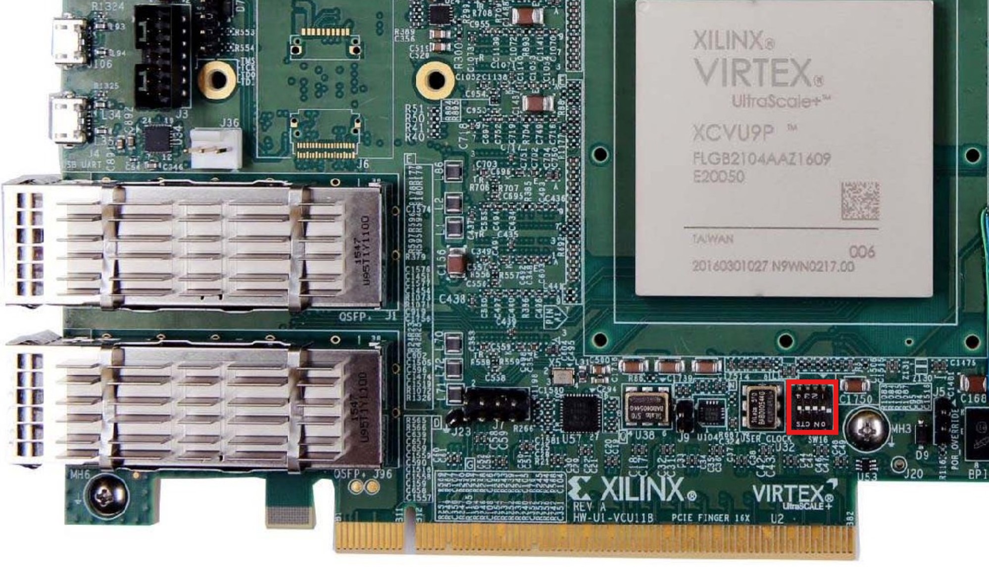
Configure switch SW16 for JTAG boot mode:
SCE (SW16-1)
M2 (SW16-2)
M1 (SW16-3)
M0 (SW16-4)
OFF
ON
OFF
ON
Connect the first Micro-USB cable to the JTAG port on the VCU118
Connect the second Micro-USB cable to the UART port on the VCU118
Plug-in an Ethernet cable from your router/switch to the Ethernet port on the FPGA board
Connect the external power supply to the evaluation board
Power on the VCU118
Observe serial console output messages on your terminal program.
Programming the board
With the board powered on, open xsct or xsdb on the host PC,
navigate to the working directory containing the required files, and
source the programming script:
~$
xsct
xsct% source run.tcl
The script will program the FPGA with the bitstream and load the Linux kernel image over JTAG. It will build the MicroBlaze system and start the boot process. This may take a few minutes to complete. Do not interrupt the process once it has started. Build logs will be printed in the terminal.
****** Software Commandline Tool (XSCT) v2025.1.0
**** SW Build 6140146 on Wed May 21 17:37:51 MDT 2025
** Copyright 1986-2022 Xilinx, Inc. All Rights Reserved.
** Copyright 2022-2025 Advanced Micro Devices, Inc. All Rights Reserved.

Warning: XSCT is deprecated and will be removed in future releases.
We recommend using the new Python command-line tool for project management and debugging:
- Run "vitis -i" for interactive mode.
- Run "vitis -s <script>" for script mode.
xsct% run.tcl
invalid command name "run.tcl"
xsct% source run.tcl
attempting to launch hw_server

****** Xilinx hw_server v2025.1
**** Build date : May  6 2025 at 15:14:51
   ** Copyright 1986-2022 Xilinx, Inc. All Rights Reserved.
   ** Copyright 2022-2025 Advanced Micro Devices, Inc. All Rights Reserved.

INFO: hw_server application started
INFO: Use Ctrl-C to exit hw_server application

INFO: To connect to this hw_server instance use url: TCP:127.0.0.1:3121

100%   29MB   1.2MB/s  00:24
Downloading Program -- /working_directory/simpleImage.vcu118_ad9213_evb.strip
      section, .text: 0x80000000 - 0x8084d05f
      section, __fdt_blob: 0x8084d060 - 0x8085d05f
      section, .rodata: 0x8085e000 - 0x80f0e357
      section, .pci_fixup: 0x80f0e358 - 0x80f108d7
      section, .builtin_fw: 0x80f108d8 - 0x80f10997
      section, __ksymtab: 0x80f10998 - 0x80f1ce9b
      section, __ksymtab_gpl: 0x80f1ce9c - 0x80f28d93
      section, __ksymtab_strings: 0x80f28d94 - 0x80f4f572
      section, __param: 0x80f4f574 - 0x80f4ff73
      section, __modver: 0x80f4ff74 - 0x80f50027
      section, __ex_table: 0x80f50030 - 0x80f5154f
      section, .notes: 0x80f51550 - 0x80f515a3
      section, .sdata2: 0x80f52000 - 0x80f51fff
      section, .data: 0x80f52000 - 0x80fffaff
      section, .data..percpu: 0x81000000 - 0x80ffffff
      section, .init.text: 0x81000000 - 0x8103046b
      section, .init.data: 0x8103046c - 0x8103373f
      section, .init.ivt: 0x81033740 - 0x81033767
      section, .init.setup: 0x81033768 - 0x81033cd7
      section, .initcall.init: 0x81033cd8 - 0x81034313
      section, .con_initcall.init: 0x81034314 - 0x8103431b
      section, .bss: 0x81035000 - 0x8106576f
      section, .init.ramfs: 0x81166000 - 0x8164855b
100%   21MB   0.1MB/s  05:25
Setting PC to Program Start Address 0x80000000
Successfully downloaded /working_directory/simpleImage.vcu118_ad9213_evb.strip
Info: MicroBlaze #0 (target 3) Running
xsct% Info: tcfchan#0 closed
You can now observe the boot process on your serial terminal.
Boot messages
Make sure to connect your UART terminal at 115200 baud, 8N1 to the VCU118 UART port before running the script to observe the boot log.
Once the system has finished booting, a login prompt will appear.
The following is what is printed in the serial console, after you have connected to the proper ttyUSB or COM port:
Ramdisk addr 0x00000000,
Compiled-in FDT at 0x8084d060
earlycon: uartlite_a0 at MMIO 0x40600000 (options '115200n8')
printk: legacy bootconsole [uartlite_a0] enabled
cma: Reserved 512 MiB at 0x8fc00000 on node -1
Linux version 6.12.0-26956-g8edd67c2e728 (george@george-precision5560) (microblazeel-xilinx-linux-gcc.real (GCC) 11.2.0, GNU ld (GNU Binutils) 2.37.20210721) #916 Mon Nov 24 16:07:26 EET 2025
setup_memory: max_mapnr: 0x7ffff
setup_memory: min_low_pfn: 0x80000
setup_memory: max_low_pfn: 0xb0000
setup_memory: max_pfn: 0xfffff
Zone ranges:
DMA      [mem 0x0000000080000000-0x00000000afffffff]
Normal   empty
HighMem  [mem 0x00000000b0000000-0x00000000ffffefff]
Movable zone start for each node
Early memory node ranges
node   0: [mem 0x0000000080000000-0x00000000ffffefff]
Initmem setup node 0 [mem 0x0000000080000000-0x00000000ffffefff]
setup_cpuinfo: initialising
setup_cpuinfo: Using full CPU PVR support
wt_msr_noirq
pcpu-alloc: s0 r0 d32768 u32768 alloc=1*32768
pcpu-alloc: [0] 0
Kernel command line: earlycon
Dentry cache hash table entries: 32768 (order: 5, 131072 bytes, linear)
Inode-cache hash table entries: 16384 (order: 4, 65536 bytes, linear)
Built 1 zonelists, mobility grouping on.  Total pages: 524287
mem auto-init: stack:off, heap alloc:off, heap free:off
SLUB: HWalign=32, Order=0-3, MinObjects=0, CPUs=1, Nodes=1
NR_IRQS: 64, nr_irqs: 64, preallocated irqs: 0
irq-xilinx: mismatch in kind-of-intr param
irq-xilinx: /amba_pl/interrupt-controller@41200000: num_irq=16, edge=0xffffc5f0
/amba_pl/timer@41c00000: irq=1
clocksource: xilinx_clocksource: mask: 0xffffffff max_cycles: 0xffffffff, max_idle_ns: 19112604467 ns
xilinx_timer_shutdown
xilinx_timer_set_periodic
sched_clock: 32 bits at 100MHz, resolution 10ns, wraps every 21474836475ns
Console: colour dummy device 80x25
printk: legacy console [tty0] enabled
printk: legacy bootconsole [uartlite_a0] disabled
Calibrating delay loop... 115.09 BogoMIPS (lpj=575488)
pid_max: default: 32768 minimum: 301
Mount-cache hash table entries: 1024 (order: 0, 4096 bytes, linear)
Mountpoint-cache hash table entries: 1024 (order: 0, 4096 bytes, linear)
Memory: 1533160K/2097148K available (8500K kernel code, 694K rwdata, 7120K rodata, 208K init, 193K bss, 39224K reserved, 524288K cma-reserved, 1310716K highmem)
devtmpfs: initialized
clocksource: jiffies: mask: 0xffffffff max_cycles: 0xffffffff, max_idle_ns: 19112604462750000 ns
futex hash table entries: 256 (order: -1, 3072 bytes, linear)
NET: Registered PF_NETLINK/PF_ROUTE protocol family
DMA: preallocated 256 KiB GFP_KERNEL pool for atomic allocations
DMA: preallocated 256 KiB GFP_KERNEL|GFP_DMA pool for atomic allocations
pps_core: LinuxPPS API ver. 1 registered
pps_core: Software ver. 5.3.6 - Copyright 2005-2007 Rodolfo Giometti <giometti@linux.it>
PTP clock support registered
jesd204: created con: id=0, topo=0, link=0, /amba_pl/spi@44a70000/ad9213@0 <-> /amba_pl/spi@44a71000/adf4371@1
jesd204: created con: id=1, topo=0, link=0, /amba_pl/spi@44a71000/hmc7044@0 <-> /amba_pl/axi-adxcvr-rx@44a60000
jesd204: created con: id=2, topo=0, link=0, /amba_pl/axi-adxcvr-rx@44a60000 <-> /amba_pl/axi-jesd204-rx@44a90000
jesd204: created con: id=3, topo=0, link=0, /amba_pl/axi-jesd204-rx@44a90000 <-> /amba_pl/spi@44a70000/ad9213@0
jesd204: /amba_pl/spi@44a70000/ad9213@0: JESD204[0:0] transition uninitialized -> initialized
jesd204: found 5 devices and 1 topologies
vgaarb: loaded
clocksource: Switched to clocksource xilinx_clocksource
NET: Registered PF_INET protocol family
IP idents hash table entries: 4096 (order: 3, 32768 bytes, linear)
tcp_listen_portaddr_hash hash table entries: 1024 (order: 0, 4096 bytes, linear)
Table-perturb hash table entries: 65536 (order: 6, 262144 bytes, linear)
TCP established hash table entries: 2048 (order: 1, 8192 bytes, linear)
TCP bind hash table entries: 2048 (order: 2, 16384 bytes, linear)
TCP: Hash tables configured (established 2048 bind 2048)
UDP hash table entries: 256 (order: 0, 4096 bytes, linear)
UDP-Lite hash table entries: 256 (order: 0, 4096 bytes, linear)
NET: Registered PF_UNIX/PF_LOCAL protocol family
RPC: Registered named UNIX socket transport module.
RPC: Registered udp transport module.
RPC: Registered tcp transport module.
RPC: Registered tcp-with-tls transport module.
RPC: Registered tcp NFSv4.1 backchannel transport module.
PCI: CLS 0 bytes, default 32
workingset: timestamp_bits=30 max_order=19 bucket_order=0
Key type cifs.idmap registered
jffs2: version 2.2. (NAND) (SUMMARY)  © 2001-2006 Red Hat, Inc.
romfs: ROMFS MTD (C) 2007 Red Hat, Inc.
bounce: pool size: 64 pages
io scheduler mq-deadline registered
io scheduler kyber registered
Serial: 8250/16550 driver, 4 ports, IRQ sharing disabled
40600000.serial: ttyUL0 at MMIO 0x40600000 (irq = 4, base_baud = 0) is a uartlite
printk: legacy console [ttyUL0] enabled
uartlite 41400000.serial: error -EINVAL: could not read current-speed
uartlite 41400000.serial: probe with driver uartlite failed with error -22
brd: module loaded
xilinx_axienet 40c00000.ethernet: missing/invalid xlnx,addrwidth property, using default
i2c_dev: i2c /dev entries driver
pca954x 0-0075: supply vdd not found, using dummy regulator
i2c i2c-0: Added multiplexed i2c bus 1
i2c i2c-0: Added multiplexed i2c bus 2
i2c i2c-0: Added multiplexed i2c bus 3
at24 4-0054: supply vcc not found, using dummy regulator
at24 4-0054: 1024 byte 24c08 EEPROM, writable, 1 bytes/write
i2c i2c-0: Added multiplexed i2c bus 4
i2c i2c-0: Added multiplexed i2c bus 5
i2c i2c-0: Added multiplexed i2c bus 6
i2c i2c-0: Added multiplexed i2c bus 7
i2c i2c-0: Added multiplexed i2c bus 8
pca954x 0-0075: registered 8 multiplexed busses for I2C switch pca9548
pca954x 0-0074: supply vdd not found, using dummy regulator
si570 9-005d: registered, current frequency 148500000 Hz
i2c i2c-0: Added multiplexed i2c bus 9
i2c i2c-0: Added multiplexed i2c bus 10
i2c i2c-0: Added multiplexed i2c bus 11
i2c i2c-0: Added multiplexed i2c bus 12
i2c i2c-0: Added multiplexed i2c bus 13
i2c i2c-0: Added multiplexed i2c bus 14
i2c i2c-0: Added multiplexed i2c bus 15
i2c i2c-0: Added multiplexed i2c bus 16
pca954x 0-0074: registered 8 multiplexed busses for I2C switch pca9548
adi_axi_adc 44a10000.backend: AXI ADC IP core (10.03.) probed
iio_dmaengine_buffer_alloc:295 width 0 (DMA width >= 256-bits ?)
hmc7044 spi1.0: PLL1: Holdover, CLKIN3 @ 125000000 Hz, PFD: 6250 kHz - PLL2: Locked @ 2500.000000 MHz
jesd204: /amba_pl/spi@44a71000/hmc7044@0,jesd204:3,parent=spi1.0: Using as SYSREF provider
axi_adxcvr_drv 44a60000.axi-adxcvr-rx: AXI-ADXCVR-RX (17.05.a) using QPLL on GTY4. Number of lanes: 16.
axi-jesd204-rx 44a90000.axi-jesd204-rx: AXI-JESD204-RX (1.07.a). Encoder 8b10b, width 4/4, lanes 16, jesd204-fsm.
axi_sysid 45000000.axi-sysid-0: AXI System ID core version (1.01.a) found
axi_sysid 45000000.axi-sysid-0: [ad9213_evb] on [vcu118] git branch <main> git <55afbcc25faf7c70505ab9d752be91ce9cb9eca4> clean [2025-05-08 19:39:25] UTC
Initializing XFRM netlink socket
NET: Registered PF_INET6 protocol family
Segment Routing with IPv6
In-situ OAM (IOAM) with IPv6
sit: IPv6, IPv4 and MPLS over IPv4 tunneling driver
NET: Registered PF_PACKET protocol family
NET: Registered PF_KEY protocol family
Key type dns_resolver registered
Key type encrypted registered
jesd204: /amba_pl/spi@44a70000/ad9213@0,jesd204:0,parent=spi0.0: JESD204[0:0] transition initialized -> probed
jesd204: /amba_pl/spi@44a70000/ad9213@0,jesd204:0,parent=spi0.0: JESD204[0:0] transition probed -> initialized
jesd204: /amba_pl/spi@44a70000/ad9213@0,jesd204:0,parent=spi0.0: JESD204[0:0] transition initialized -> probed
jesd204: /amba_pl/spi@44a70000/ad9213@0,jesd204:0,parent=spi0.0: JESD204[0:0] transition probed -> idle
jesd204: /amba_pl/spi@44a70000/ad9213@0,jesd204:0,parent=spi0.0: JESD204[0:0] transition idle -> device_init
jesd204: /amba_pl/spi@44a70000/ad9213@0,jesd204:0,parent=spi0.0: JESD204[0:0] transition device_init -> link_init
jesd204: /amba_pl/spi@44a70000/ad9213@0,jesd204:0,parent=spi0.0: JESD204[0:0] transition link_init -> link_supported
jesd204: /amba_pl/spi@44a70000/ad9213@0,jesd204:0,parent=spi0.0: JESD204[0:0] transition link_supported -> link_pre_setup
jesd204: /amba_pl/spi@44a70000/ad9213@0,jesd204:0,parent=spi0.0: JESD204[0:0] transition link_pre_setup -> clk_sync_stage1
jesd204: /amba_pl/spi@44a70000/ad9213@0,jesd204:0,parent=spi0.0: JESD204[0:0] transition clk_sync_stage1 -> clk_sync_stage2
jesd204: /amba_pl/spi@44a70000/ad9213@0,jesd204:0,parent=spi0.0: JESD204[0:0] transition clk_sync_stage2 -> clk_sync_stage3
jesd204: /amba_pl/spi@44a70000/ad9213@0,jesd204:0,parent=spi0.0: JESD204[0:0] transition clk_sync_stage3 -> link_setup
jesd204: /amba_pl/spi@44a70000/ad9213@0,jesd204:0,parent=spi0.0: JESD204[0:0] transition link_setup -> opt_setup_stage1
jesd204: /amba_pl/spi@44a70000/ad9213@0,jesd204:0,parent=spi0.0: JESD204[0:0] transition opt_setup_stage1 -> opt_setup_stage2
jesd204: /amba_pl/spi@44a70000/ad9213@0,jesd204:0,parent=spi0.0: JESD204[0:0] transition opt_setup_stage2 -> opt_setup_stage3
jesd204: /amba_pl/spi@44a70000/ad9213@0,jesd204:0,parent=spi0.0: JESD204[0:0] transition opt_setup_stage3 -> opt_setup_stage4
jesd204: /amba_pl/spi@44a70000/ad9213@0,jesd204:0,parent=spi0.0: JESD204[0:0] transition opt_setup_stage4 -> opt_setup_stage5
jesd204: /amba_pl/spi@44a70000/ad9213@0,jesd204:0,parent=spi0.0: JESD204[0:0] transition opt_setup_stage5 -> clocks_enable
jesd204: /amba_pl/spi@44a70000/ad9213@0,jesd204:0,parent=spi0.0: JESD204[0:0] transition clocks_enable -> link_enable
ad9213 spi0.0: AD9213 PLL LOCKED
jesd204: /amba_pl/spi@44a70000/ad9213@0,jesd204:0,parent=spi0.0: JESD204[0:0] transition link_enable -> link_running
jesd204: /amba_pl/spi@44a70000/ad9213@0,jesd204:0,parent=spi0.0: JESD204[0:0] transition link_running -> opt_post_running_stage
Freeing unused kernel image (initmem) memory: 208K
This architecture does not have kernel memory protection.
Run /init as init process
with arguments:
   /init
with environment:
   HOME=/
   TERM=linux
Starting syslogd: OK
Starting klogd: OK
Running sysctl: OK
Saving 256 bits of non-creditable seed for next boot
Starting network: udhcpc: started, v1.36.1
xilinx_axienet 40c00000.ethernet eth0: PHY [axienet-40c00000:03] driver [TI DP83867] (irq=POLL)
xilinx_axienet 40c00000.ethernet eth0: configuring for phy/sgmii link mode
random: crng init done
udhcpc: broadcasting discover
xilinx_axienet 40c00000.ethernet eth0: Link is Up - 1Gbps/Full - flow control off
udhcpc: broadcasting discover
udhcpc: broadcasting discover
udhcpc: broadcasting discover
udhcpc: broadcasting discover
udhcpc: broadcasting discover
udhcpc: broadcasting discover
udhcpc: no lease, failing
Starting dropbear sshd: OK
Starting IIO Server Daemon

Welcome to Buildroot
buildroot login:
Login information
user:
rootpassword:
analog
Useful commands
The below commands are to be run in the serial terminal connected to the FPGA.
To find out the IP of the FPGA board, run the following command and take the IP specified at “eth0 inet”:
~$
ifconfig
To find the IIO devices detected, run:
~$
iio_info | grep iio:device
To power off the system cleanly, run the following command and wait for the final message before switching off the board:
~$
poweroff
Important
This system boots from a ramdisk. It is a MicroBlaze soft processor. The filesystem is not persistent. Any changes made at runtime will be lost. At the same time, the system cannot reboot, so the only way to restart the system is to reprogram the FPGA and reload the kernel image using the steps above.
IIO Oscilloscope
IIO Oscilloscope is a cross-platform is a cross-platform GUI application that can connect to the board remotely over the network and capture data from IIO devices.
Note
A signal generator is required to provide an analog input signal to the evaluation board’s RF SMA input connector before capturing data. The captures below were obtained with a signal generator set to: 20 MHz, 1.5 Vpp. The time domain capture uses a sample size of 4096 samples. The frequency domain capture uses an FFT size of 65536.
To connect, open IIO Oscilloscope on the host PC, go to
Setting, Connect, check Manual option and enter the URI using the board
IP address obtained from ifconfig:
ip:<board-ip>
Press Refresh to list the available IIO devices (FRU Info, Context Description, Context Attributes and IIO Devices fields should display information about the connected devices), then press Connect.
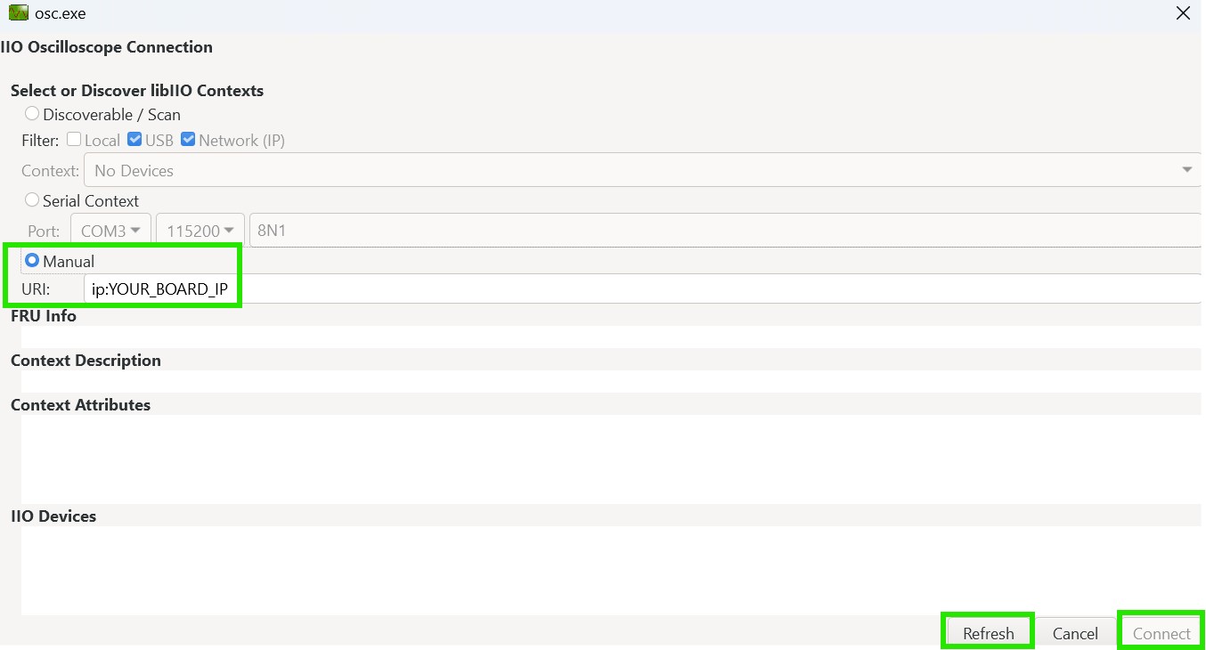
Once connected, select the AD9213 device and use the Capture window to acquire and display ADC samples.
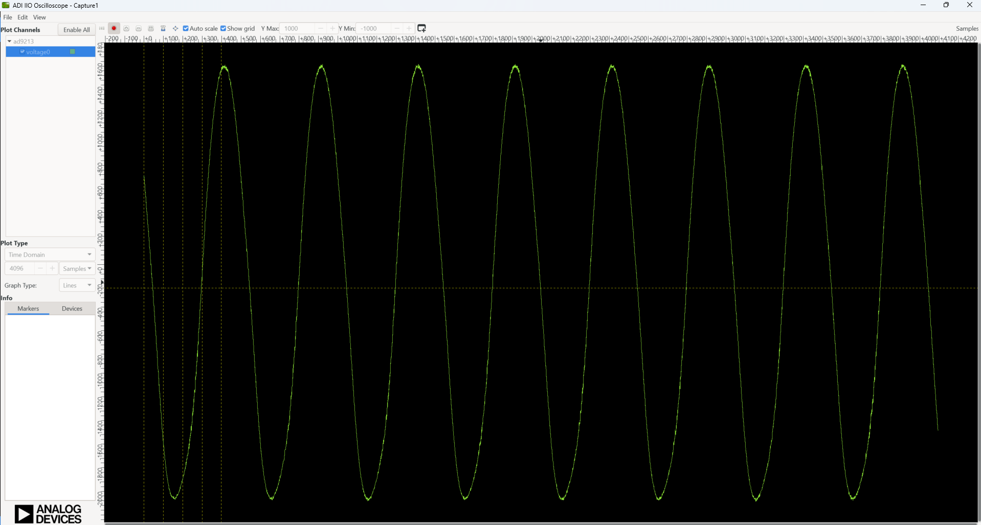
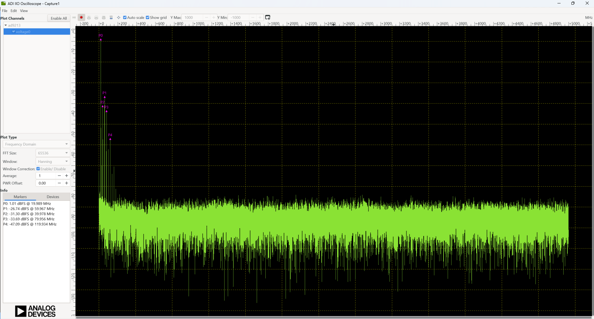
Figure 7 AD9213 frequency domain capture in IIO Oscilloscope