User guide
Hardware guide
Hardware configuration
The EVAL-AD9213 evaluation board does not natively support JTAG boot. To enable it, the board must be inserted into the ZX180V-HSPC FMC VITA 57.4 Mezzanine card breakout adapter, and a wire must be soldered between pins D30 and D31 on the breakout adapter. This connection bridges the TDI and TDO signals, which is required to close the JTAG chain.
Once the wire is in place, insert the FMC+ breakout adapter (with the evaluation board mounted on it) into the FMC+ connector of the AMD Xilinx VCU118.
On the VCU118, configure switch SW16 for JTAG boot mode by setting:
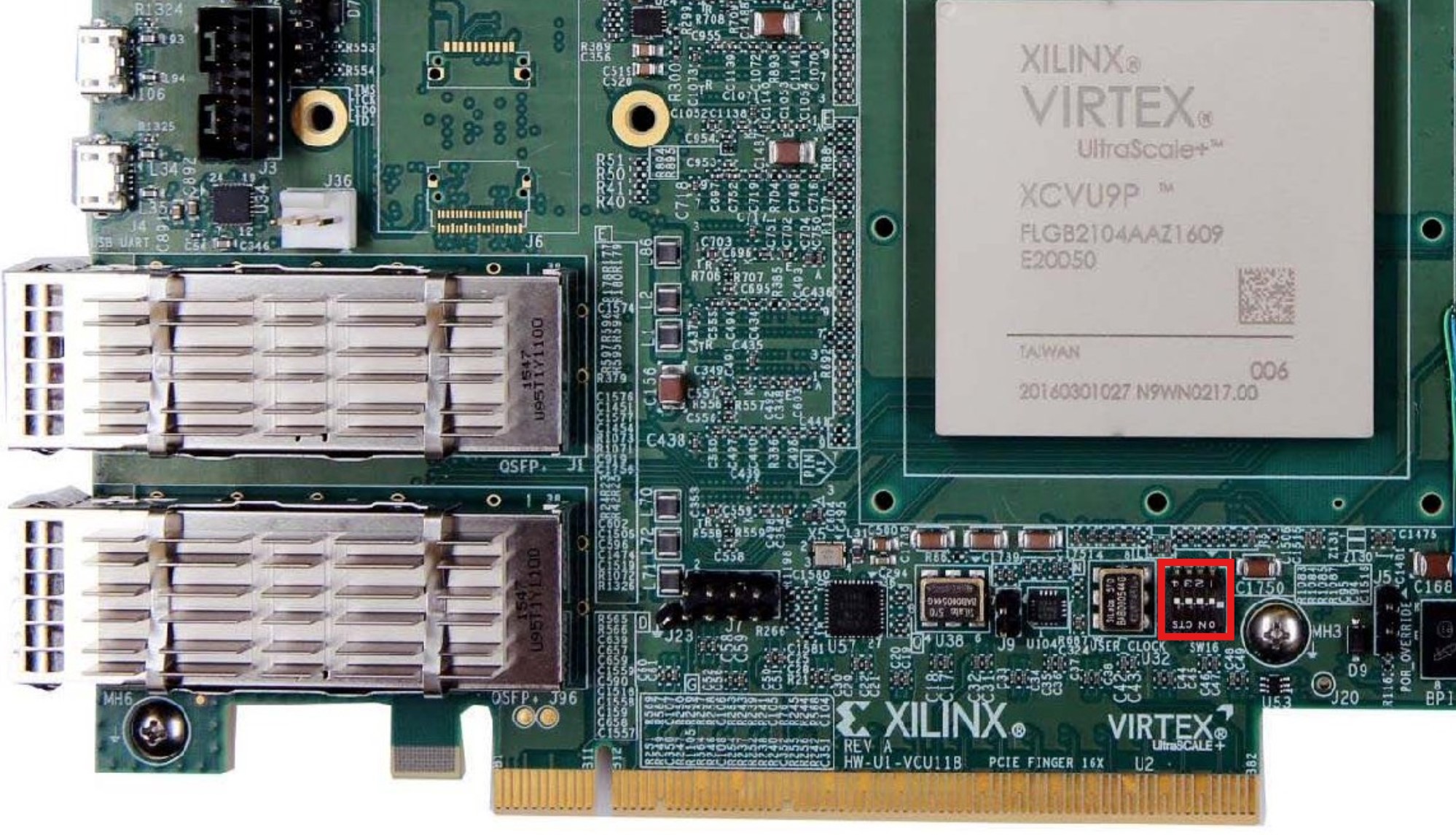
SCE (SW16-1) |
M2 (SW16-2) |
M1 (SW16-3) |
M0 (SW16-4) |
|---|---|---|---|
OFF |
ON |
OFF |
ON |
Power supply
The EVAL-AD9213 requires an external power supply. Connect it before powering on the board. The FMC+ connection to the AMD Xilinx VCU118 carries the digital interface signals, while the evaluation board relies on its own dedicated supply rail.
Analog inputs
The evaluation board exposes an analog RF input via SMA connector. Feed a wideband RF signal appropriate for the frequency range and power level specified in the AD9213 datasheet. Use a low-noise signal source for best dynamic range results.
Schematic, PCB Layout, Bill of Materials
Design support files for the EVAL-AD9213 evaluation board, including schematics, PCB layout, and bill of materials, are available on the AD9213 product page.
Software guide
The EVAL-AD9213 boots Linux using a JTAG-based flow.
The board is programmed via Xilinx’s xsct or xsdb tool using
a provided TCL script.
The evaluation board is supported through the Linux IIO subsystem. Once booted, IIO-based tools can be used to interact with the device: