Intel Stratix 10 SX Quick start
All the products described on this page include ESD (electrostatic discharge) sensitive devices. Electrostatic charges as high as 4000V readily accumulate on the human body or test equipment and can discharge without detection. Although the boards feature ESD protection circuitry, permanent damage may occur on devices subjected to high-energy electrostatic discharges. Therefore, proper ESD precautions are recommended to avoid performance degradation or loss of functionality. This includes removing static charge on external equipment, cables, or antennas before connecting to the device.
This guide provides instructions on how to bring up the AD9213-DUAL-EBZ on in Synchronized 10G Mode or Interleaved 20G Mode to enable data capture and visualization in IIO Oscilloscope and VisualAnalog. The AD9213 Manual Calibration and Interleaving Guide provides extra detail.
Required equipment and hardware
RF Power Splitter for splitting the test tone to apply two equal signals to each of the two ADCs
Phase matched coaxial cables to connect the power splitter to the ADC input board connectors
RF Balun for single-ended-to-differential conversion of the 500 MHz reference clock
Coax cables for the 500 MHz reference clock connections
Signal generators:
Analog signal source: frequency and power requirements depend on the tests to be performed; a bandpass filter is often used for single tone tests
500 MHz Reference Clock source: should have very low phase noise and be capable of supplying a 5 dBm, 500 MHz clock signal
PC running Windows with at least 2 USB ports and an Ethernet port, with:
One mini-USB cable
One micro-USB cable
One Ethernet cable
Helpful documents
Required software
-
VisualAnalog Canvas for AD9213-DUAL-EBZ (supplied by ADI)
ADI libiio repository (for IIO Client block in provided VisualAnalog Canvas)
ADI software deliverables
The link above contains the following:
FPGA binary for the Stratix 10 SX SoC
SD Card images containing IIO libraries and a system initialization sequence
Example scripts for Synchronization and Interleaving
PDF Documents: Software License, Quickstart Guide, Manual Calibration Guide
VisualAnalog (software from analog.com) Canvases for viewing FFTs
Serial terminal of your choice to connect to the board via UART
Setup and connection
Perform all connections with power and signal generators OFF, connecting the boards as shown in the typical setup figure above.
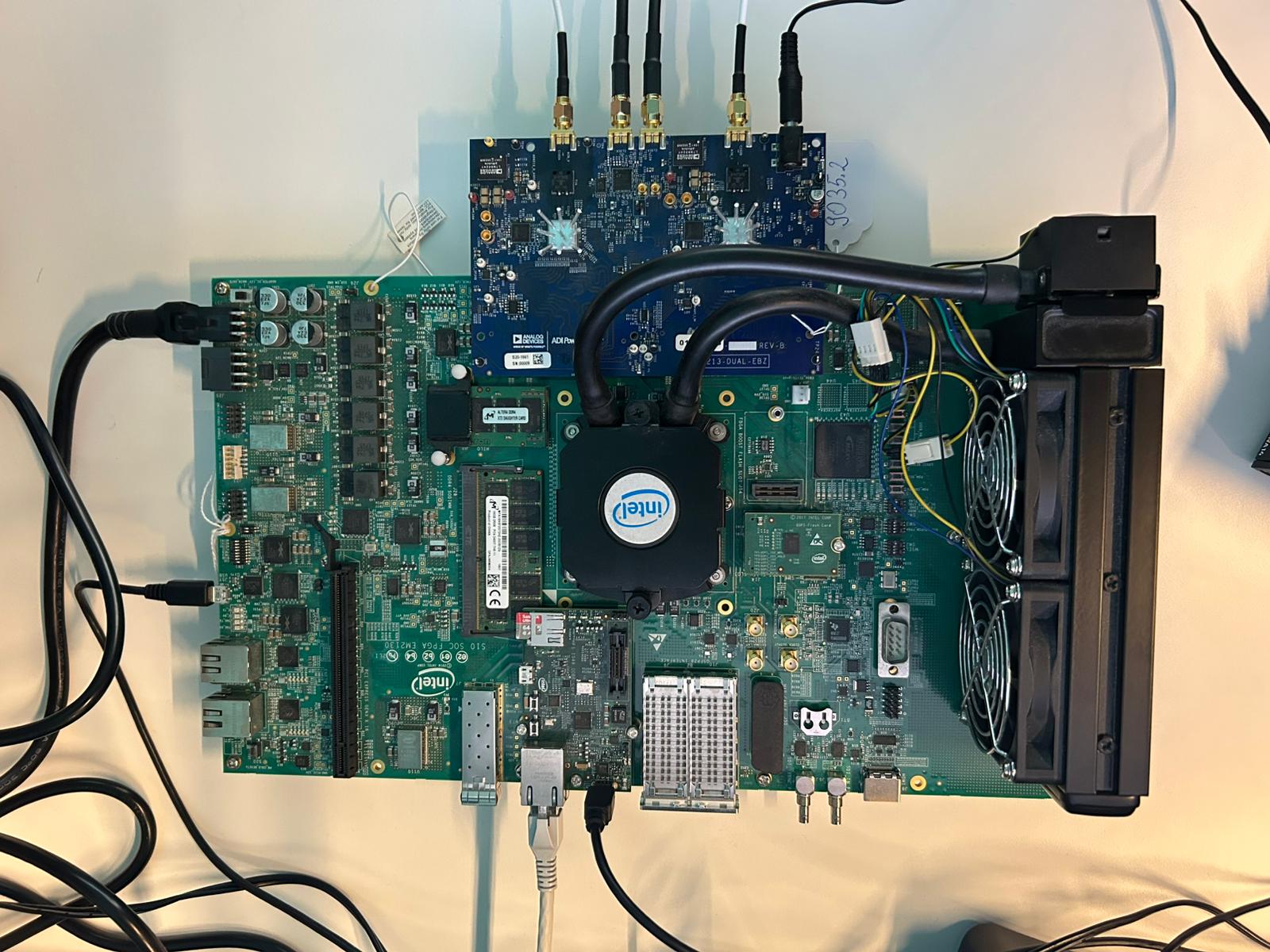
Figure 2 AD9213-DUAL-EBZ and Intel Stratix 10 SX Board - Setup
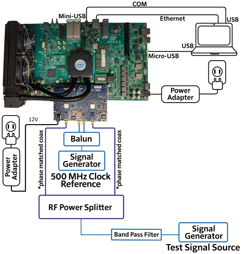
Figure 3 AD9213-DUAL-EBZ and Intel Stratix 10 SX Board - Typical Setup
Board switch configuration
Configure the switches on the Stratix 10 SX SoC FPGA board as follows:
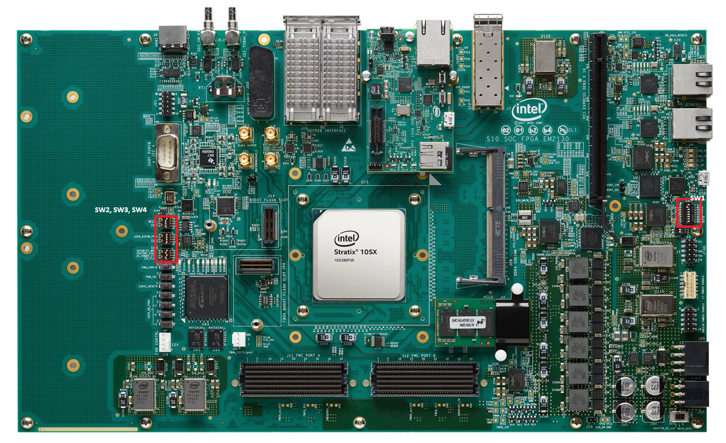
SW1
S10 |
M10B |
FMCA |
FMCB |
PCIE |
MSTR0 |
MSTR1 |
MSTR2 |
|---|---|---|---|---|---|---|---|
OFF |
ON |
ON |
ON |
ON |
ON |
ON |
ON |
SW2 - MSEL
Configure SW2 according to the desired boot mode:
Switch Bit |
1 (MSEL0) |
2 (MSEL1) |
3 (MSEL2) |
4 (Not Used) |
|---|---|---|---|---|
JTAG Mode |
ON |
ON |
ON |
OFF |
QSPI Mode |
ON |
OFF |
OFF |
OFF |
SW3 - USR_DIPSW_FPGA
PIN1 |
PIN2 |
PIN3 |
PIN4 |
|---|---|---|---|
OFF |
OFF |
OFF |
OFF |
SW4
I2C FLAG |
DC_POWER CTRL |
FACTORY LOAD |
SECURITY MODE |
|---|---|---|---|
ON |
OFF |
OFF |
ON |
SD card preparation
Download the ADI Linux Image (
image_2021-07-28-ADI-Kuiper-full.zip) available under ADI kuiper repository (releases).Program a blank SD card (at least 16 GB) with the downloaded image using the instructions in Using Kuiper Images.
Note
Once the image is programmed, eject the SD card and re-insert it. The SD card will already include a few folders in its BOOT partition; those can be ignored for this setup.
For the SD card to boot correctly, place the
socfpga_stratix10_socdk.dtband theu-boot.itbfiles provided in the SD card folder into the top-level directory (BOOT D:). In addition to this, also place one of theImagefiles based on use case:From the Dual 10G Image folder - for Synchronized 10G Mode
From the Single 20G Image folder - for Interleaved 20G Mode
Replace the SD card on the Stratix 10 SX SoC board with the SD card you just programmed.
Power-up and signal generators
Power up the boards and configure the signal generators:
Start with low test signal power (about 0 dBm); this can be adjusted later as desired.
For the reference clock signal, set the generator power to 5 dBm.
UART connection
Connect the Micro-USB port of the Stratix 10 SX SoC board to the host PC. Use a serial terminal application of choice (PuTTY, Tera Term, etc) to open the corresponding COM port with the following settings: 115200 baud, 8N1.
Programming the board
Start Quartus Prime Programmer 19.3. The software should auto-detect the Stratix 10H SoC Evaluation Board in the Hardware Setup section at the top. If it does not appear automatically, select it manually.
Once the board has been detected, click Add File.
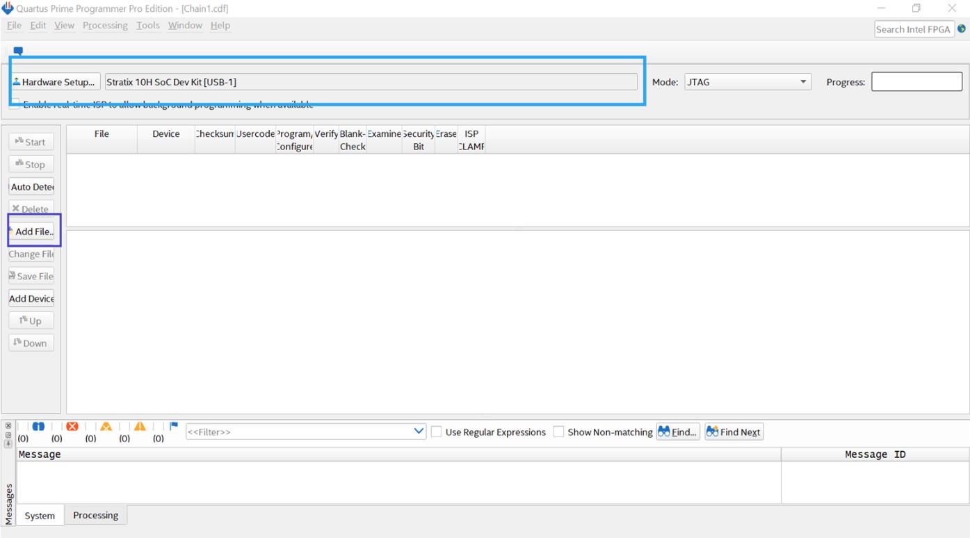
Figure 5 Setting up the Quartus Programmer to program the FPGA image
Navigate to the location of the ADI-provided FPGA program (
ad9213_dual_ebz_s10soc_hps_20_4.sof), select the file, and click Open.Note
It will take a few seconds for the file to be added and the FPGA device to appear on screen.
Click Start and wait for the programmer to complete.
Note
Programming the FPGA also triggers the Linux boot on the HPS. The COM console provides updates on the progress of the boot.
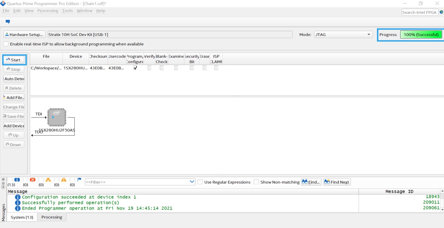
Figure 6 Using the Quartus Programmer to program the FPGA image
The COM console will display a verbose running of the initialization scripts, at the end of which the setup will be ready.
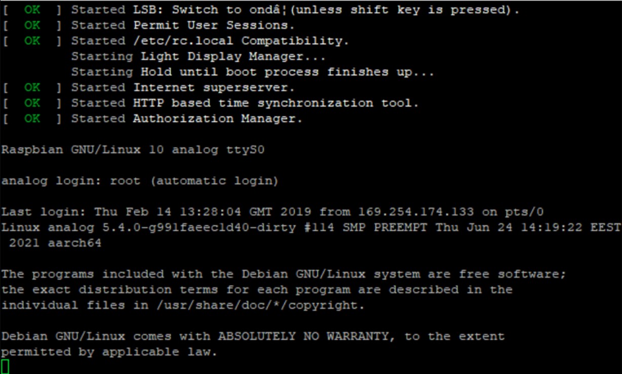
Figure 7 COM console once the boot process and initialization are complete
Obtain the board IP address by running
ifconfigin the console.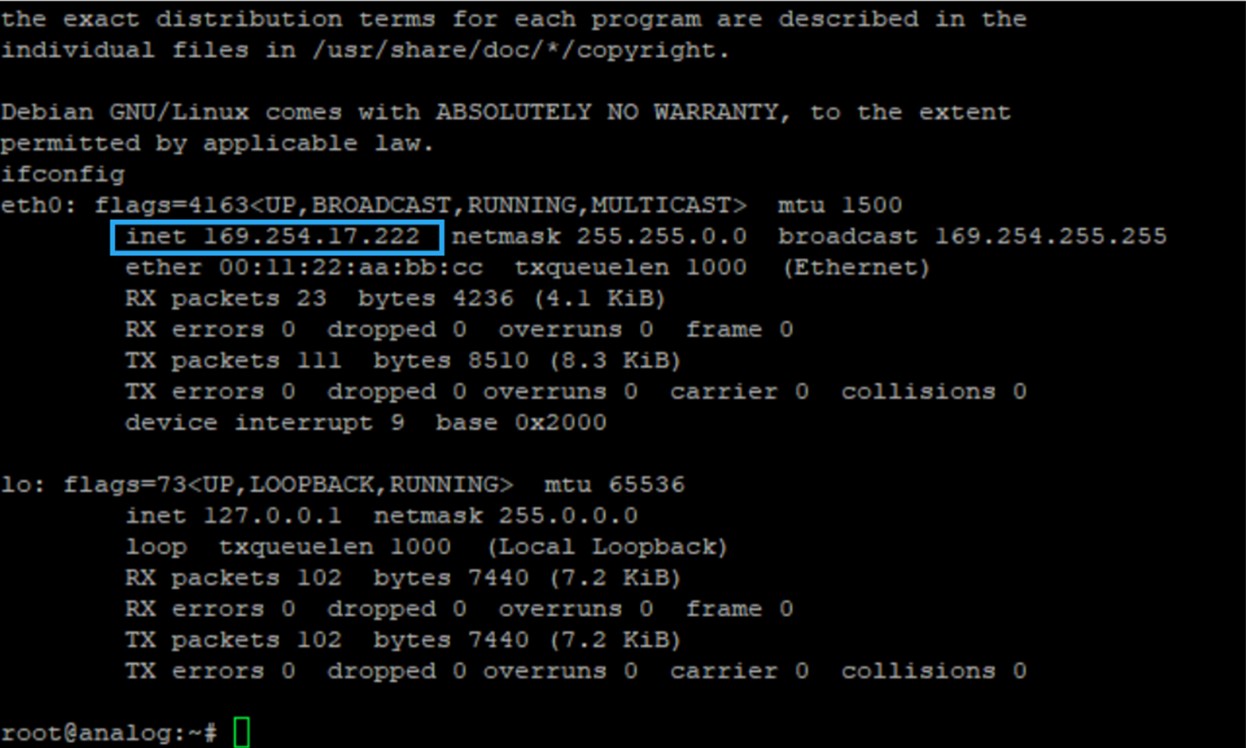
Figure 8 Using ifconfig to obtain the IP address of the Stratix 10 SX SoC board Ethernet connection
SSH connection (Interleaved 20G Mode only)
For Interleaved 20G Mode, open an SSH connection to the board to run SPI scripts. Use your terminal application with the following settings:
Connection Type: SSH
Host Name: IP address of the Stratix 10 board, obtained in the previous step
Port:
22
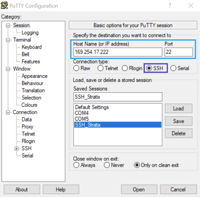
Figure 9 Opening an SSH connection to the Stratix 10 SX SoC board
Login credentials:
Login:
rootPassword:
analog
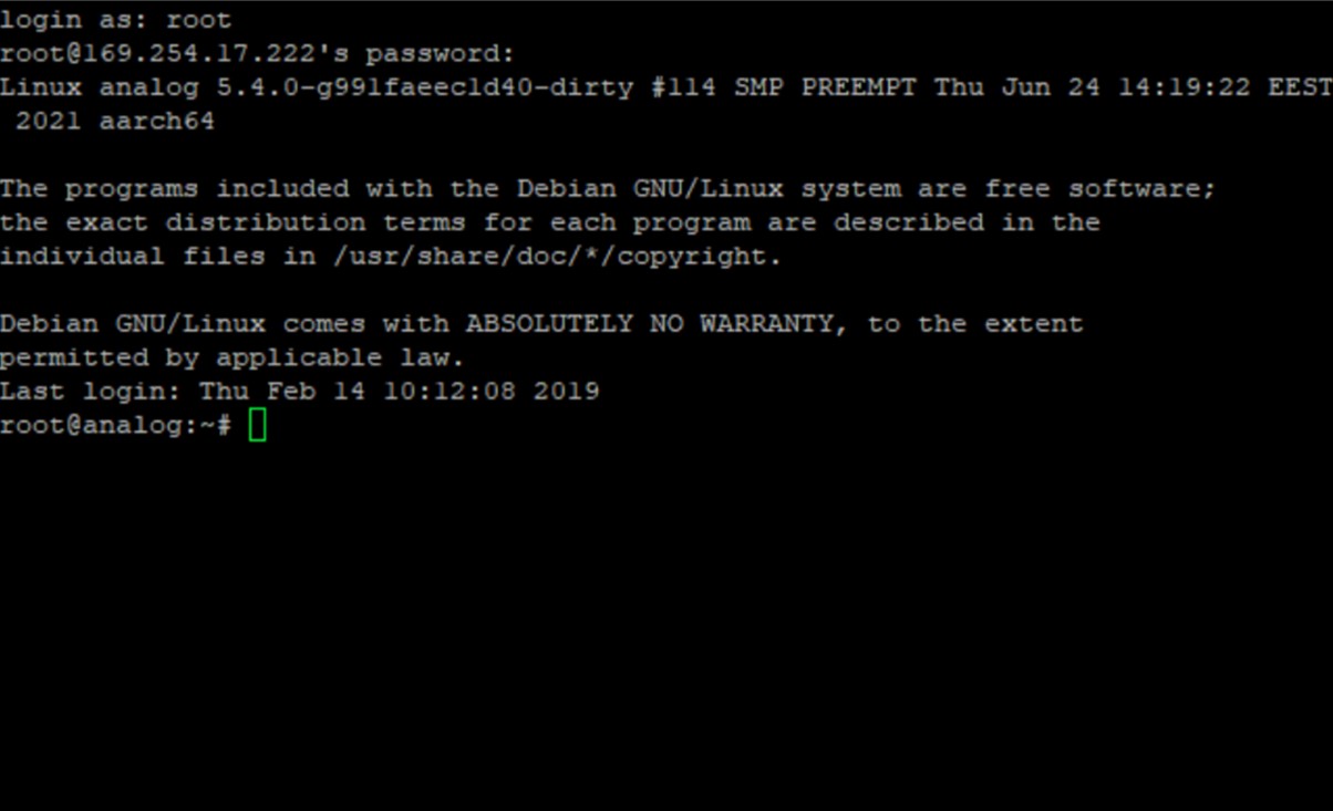
Figure 10 Connection after login ready to access the components on the board via SPI
An example script for SPI reads and writes can be provided on request.
IIO Oscilloscope
Go to the Connect tab, select Manual, enter the IP address of the board prefaced by
ip:in the URL input box, and click Refresh.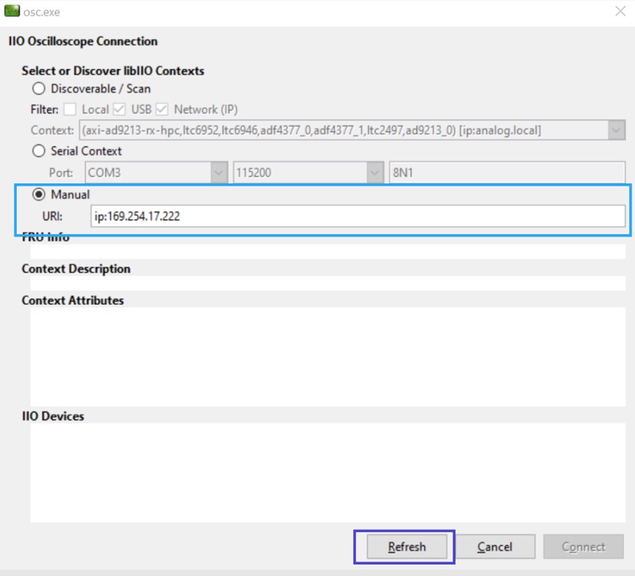
Once you click Refresh, all the IIO devices on the AD9213-DUAL-EBZ — including the two AD9213s and the other clock chips — will show up. Click Connect. On subsequent connections with the same setup, IIO Oscilloscope will auto-detect the configuration automatically.
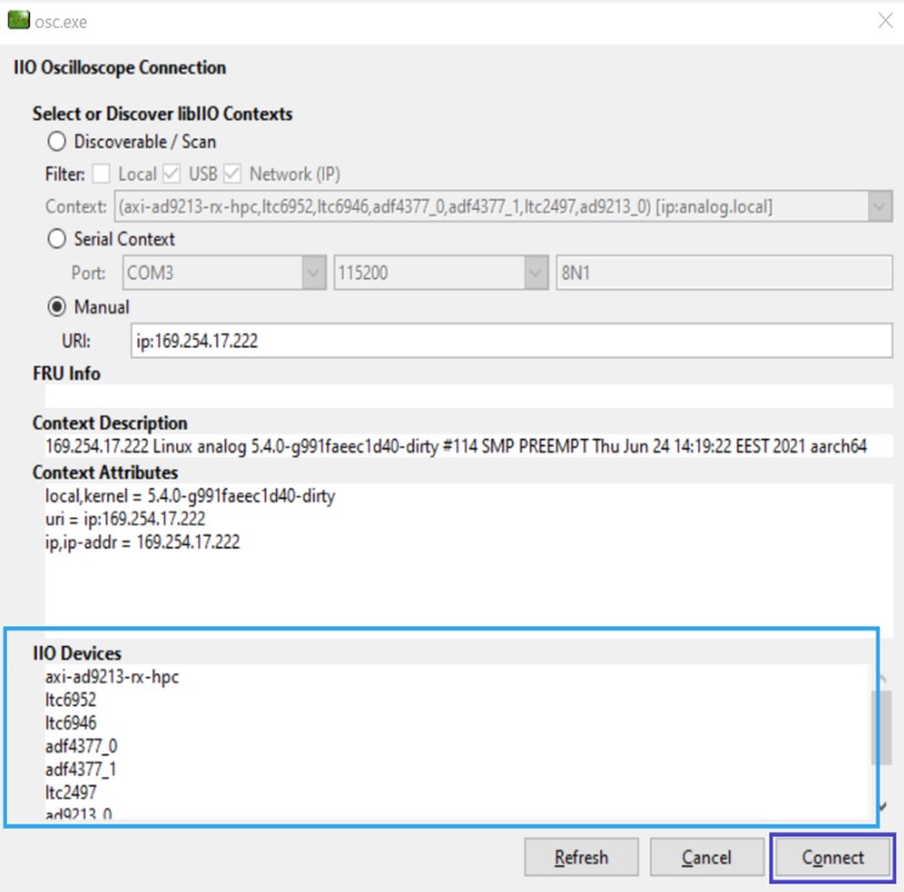
Figure 12 All devices on the evaluation board ready to connect to IIO Oscilloscope
After connecting, an SPI Controller window and a Plotting window will open.
The SPI Controller window allows reading and writing individual registers for any device on the board. This is optional — the automatic startup configuration has already run on boot.
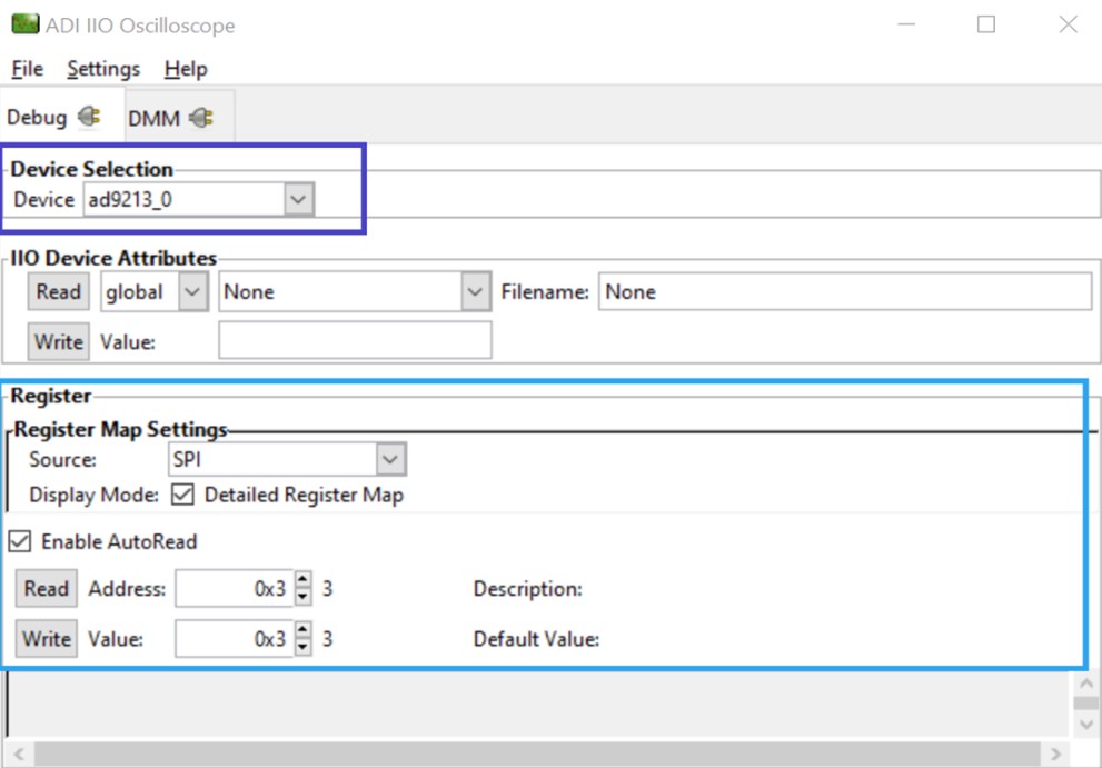
Figure 13 Using the IIO Oscilloscope Controller view to read and write SPI
Use the Plotting window to capture data from one AD9213 at a time or from both simultaneously. The selection of the AD9213 and the number of samples can be made using the panels on the left. The tool allows both time domain and frequency domain captures.
Note
In Interleaved 20G Mode, voltage 0 (channel 0) represents data from both
ad9213_0andad9213_1as a combined waveform or FFT.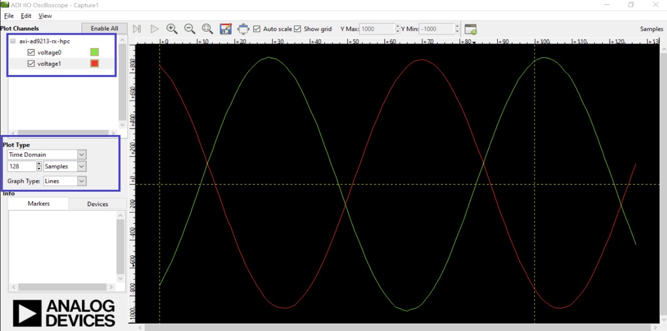
Figure 14 Using the IIO Oscilloscope Plotting view to plot separate time domain outputs from each AD9213 (Ain = 136 MHz @ 5 dBm)
For more detailed frequency domain analysis, use a VisualAnalog Canvas as described in the next section.
VisualAnalog
One-time IIO installations before running VisualAnalog (only needed if the ADI-provided VisualAnalog Canvas will be used):
Install ADI libiio repository (needed to use the IIO Client block in VisualAnalog)
Install the IIO Plugin for VisualAnalog
Synchronized 10G Mode
Go to the Existing tab and browse to the location of the
Dual9213_IIOScope_FFT.vaccanvas. Select the canvas and click Open.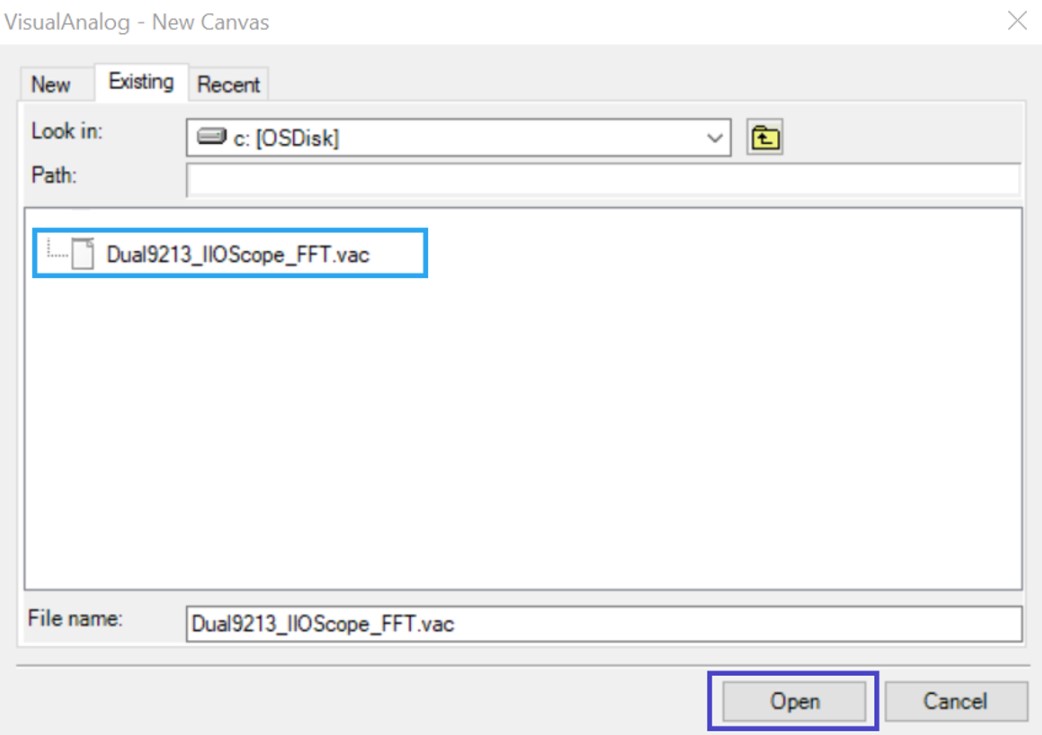
Figure 15 Opening the VisualAnalog Canvas to plot FFTs for the dual AD9213s (Synchronized 10G Mode)
Once the canvas is open, open the settings for the IIO Client module. Enter the IP address for the Stratix 10 SX SoC board, the sampling frequency, the sample size per AD9213, and enable both AD9213s. Click OK.
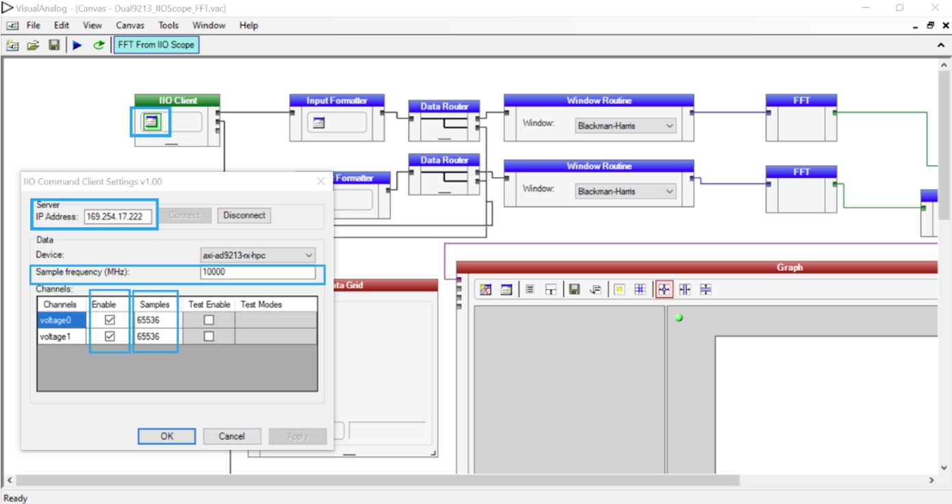
Figure 16 Setting up the VisualAnalog Canvas for capture for the dual AD9213s (Synchronized 10G Mode)
The canvas is now ready to capture FFTs for each of the AD9213s. Click Play to capture. In addition to the FFT plot and its analysis, the canvas also displays sample data for each AD9213.
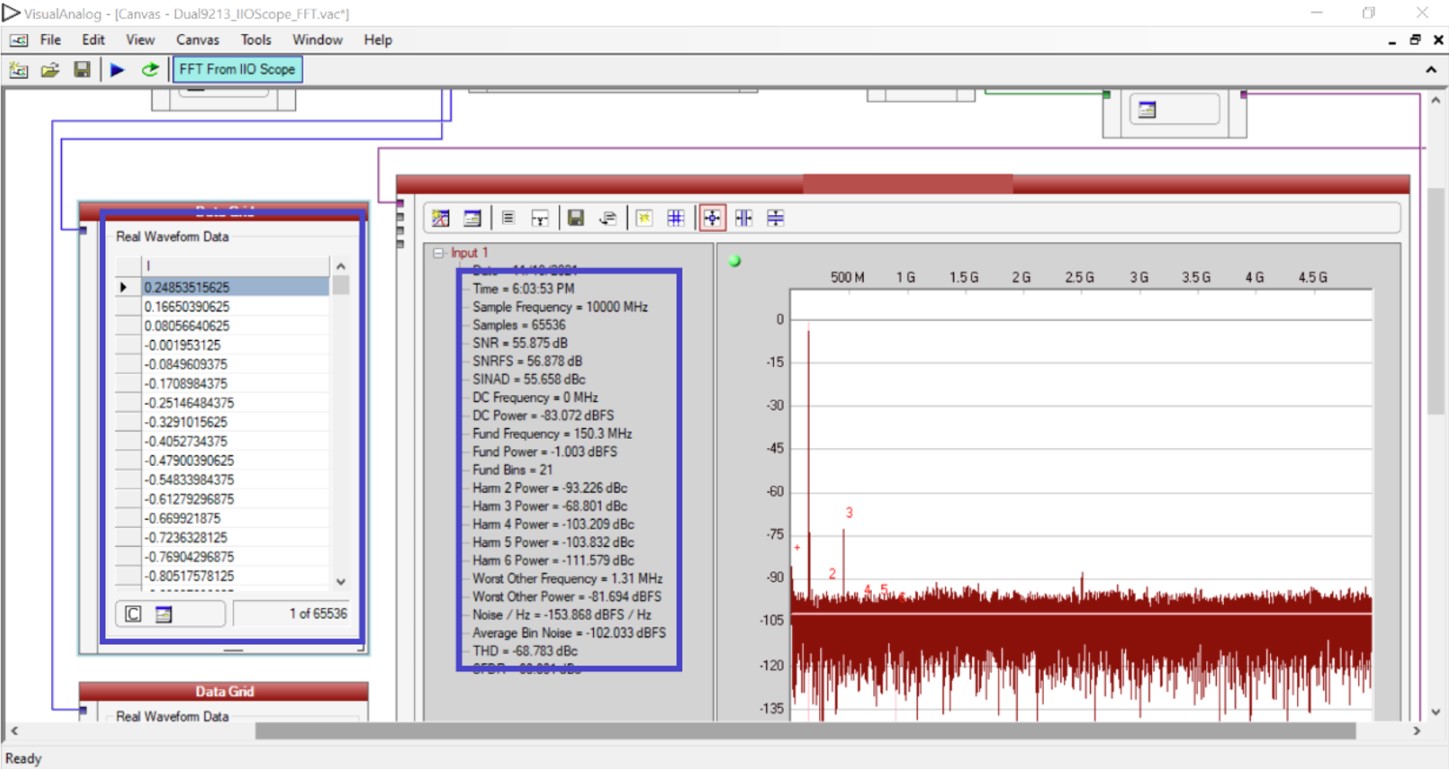
Figure 17 VisualAnalog canvas FFT capture, analysis and sample data for AD9213_0 (150.3 MHz @ 14.90 dBm)
Interleaved 20G Mode
Go to the Existing tab and browse to the location of the
Dual9213_Interleaved20G_FFT.vaccanvas. Select the canvas and click Open.Once the canvas is open, open the settings for the IIO Client module. Enter the IP address for the Stratix 10 SX SoC board, set the sampling frequency to
20000, the sample size to65536, and enable the datapath (shows up at Channel 0, but contains a sample interleaved stream of data from both AD9213s). Click OK.Note
Before you are ready to capture, the two AD9213s need to be gain and timing aligned and the sample clock to one AD9213 needs to be inverted with respect to the other.
Use the instructions in the AD9213 Manual Calibration and Interleaving Guide to run the example scripts in the SSH connection environment you opened to the board to align and interleave.
The canvas is now ready to capture an FFT. Click Play to capture.
In addition to the FFT plot and its analysis, the canvas also displays sample data.
Building from source
This section describes how to build all software components from source for the Intel Stratix 10 SX SoC platform.
Get toolchain
Download and configure the AArch64 cross-compilation toolchain:
~$
mkdir tools
~$
cd tools
~/tools$
wget https://armkeil.blob.core.windows.net/developer/Files/downloads/gnu-a/10.3-2021.07/binrel/gcc-arm-10.3-2021.07-x86_64-aarch64-none-linux-gnu.tar.xz
~/tools$
tar xvf gcc-arm-10.3-2021.07-x86_64-aarch64-none-linux-gnu.tar.xz
~/tools$
export CROSS_COMPILE=/home/analog/tools/gcc-arm-10.3-2021.07-x86_64-aarch64-none-linux-gnu/bin/aarch64-none-linux-gnu-
~/tools$
export ARCH=arm64
~/tools$
cd ~
Build Linux kernel
~$
git clone https://github.com/analogdevicesinc/linux
~$
cd linux
~/linux$
git checkout altera_adxcvr_master
~/linux$
make adi_stratix10_defconfig
~/linux$
make Image
~/linux$
make altera/socfpga_stratix10_socdk_ad9213_dual.dtb
~/linux$
cp arch/arm64/boot/Image /media/analog/BOOT/
~/linux$
cp arch/arm64/boot/dts/altera/socfpga_stratix10_socdk_ad9213_dual.dtb \
  /media/analog/BOOT/socfpga_stratix10_socdk.dtb
~/linux$
cd ~
Build ARM Trusted Firmware
~$
git clone https://github.com/altera-opensource/arm-trusted-firmware
~$
cd arm-trusted-firmware
~/arm-trusted-firmware$
git checkout rel_socfpga_v2.6.0_22.07.02_pr
~/arm-trusted-firmware$
make bl31 PLAT=stratix10 DEPRECATED=1
~/arm-trusted-firmware$
cd ~
Build U-Boot and copy u-boot.itb to SD card
~$
git clone https://github.com/altera-opensource/u-boot-socfpga
~$
cd u-boot-socfpga
~/u-boot-socfpga$
git checkout rel_socfpga_v2022.01_22.11.02_pr
~/u-boot-socfpga$
ln -sf ../arm-trusted-firmware/build/stratix10/release/bl31.bin .
~/u-boot-socfpga$
sed -i \
  's/earlycon panic=-1/earlycon panic=-1 console=ttyS0,115200 root=\/dev\/mmcblk0p2 rw rootwait/g' \
  configs/socfpga_stratix10_defconfig
~/u-boot-socfpga$
sed -i '/^CONFIG_NAND_BOOT=y/d' configs/socfpga_stratix10_defconfig
~/u-boot-socfpga$
sed -i '/^CONFIG_SPL_NAND_SUPPORT=y/d' configs/socfpga_stratix10_defconfig
~/u-boot-socfpga$
sed -i '/^CONFIG_CMD_UBI=y/d' configs/socfpga_stratix10_defconfig
~/u-boot-socfpga$
echo 'CONFIG_USE_BOOTCOMMAND=y' >> configs/socfpga_stratix10_defconfig
~/u-boot-socfpga$
echo 'CONFIG_BOOTCOMMAND="bridge enable 0xf; setenv ethaddr 00:15:17:ab:cd:ef; load mmc 0:1 ${kernel_addr_r} Image; load mmc 0:1 ${fdt_addr_r} socfpga_stratix10_socdk.dtb; booti ${kernel_addr_r} - ${fdt_addr_r}"' \
  >> configs/socfpga_stratix10_defconfig
~/u-boot-socfpga$
make socfpga_stratix10_defconfig
~/u-boot-socfpga$
sed -i \
  '/4GB/,/0x80000000>;/creg = <0 0x00000000 0 0x80000000>;' \
  arch/arm/dts/socfpga_stratix10_socdk.dts
~/u-boot-socfpga$
make
~/u-boot-socfpga$
cp u-boot.itb /media/analog/BOOT/
~/u-boot-socfpga$
cd ~
Generate .sof and .jic files
~$
git clone https://github.com/analogdevicesinc/hdl
~$
cd hdl/projects/ad9213_dual_ebz/s10soc
~/hdl/projects/ad9213_dual_ebz/s10soc$
make
Building ad9213_dual_ebz_s10soc [/home/analog/hdl/projects/ad9213_dual_ebz/s10soc/ad9213_dual_ebz_s10soc_quartus.log] ... OK
~/hdl/projects/ad9213_dual_ebz/s10soc$
quartus_pfg -c ad9213_dual_ebz_s10soc.sof \
  -o hps_path=../../../../u-boot-socfpga/spl/u-boot-spl-dtb.hex \
  ad9213_dual_ebz_s10soc_hps.sof
~/hdl/projects/ad9213_dual_ebz/s10soc$
quartus_pfg -c ad9213_dual_ebz_s10soc_hps.sof \
  ad9213_dual_ebz_s10soc_hps.jic \
  -o device=MT25QU02G \
  -o flash_loader=1SX280HU2F50E1VGAS