User Guide
People who follow the flow that is outlined have a much better experience with things. However, like many things, documentation is never as complete as it should be. If you have any questions, feel free to ask on our EngineerZone forums.
Hardware guide
Power supply
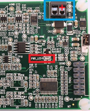
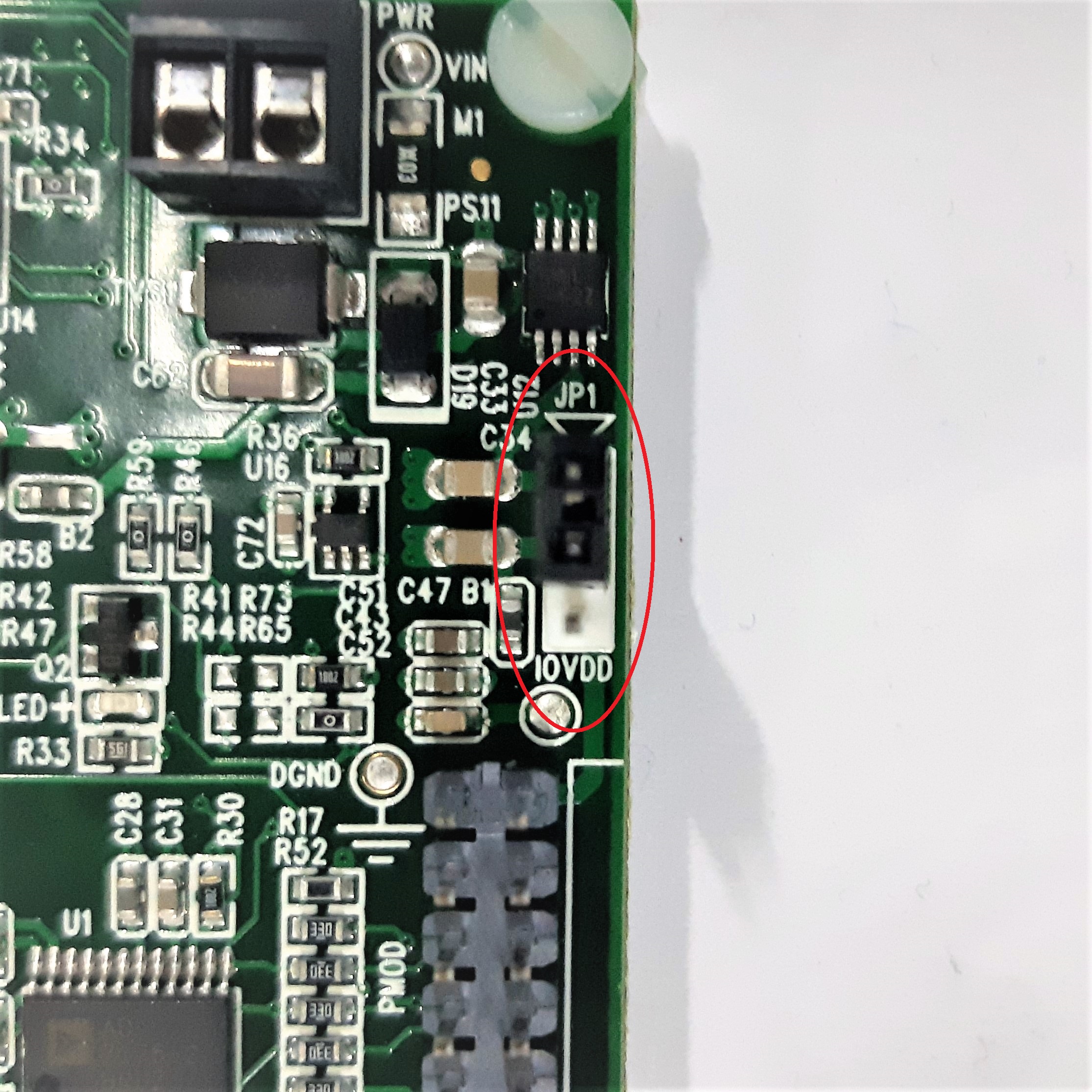
EVAL-CN0363-PMDZ requires an external DC power supply in the range of 6V to 12V fed in the screw terminal. Please take note of the polarity indicated in the figure below. The fastest way to tell the EVAL-CN0363-PMDZ board is powered is by seeing if LED labeled PWR_LED is illuminated. The analog portion of the circuit is supplied by AVDD = 5 V from an ADP7102 low dropout regulator. The digital portion of the circuit is supplied by IOVDD = 3.3 V developed from an ADP1720 low dropout regulator. Alternatively, IOVDD can be supplied from the PMOD connector, VCC, via a link option. The 2.5 V reference voltage is supplied by the internal 2.5 V reference of the AD7175-2 ADC.
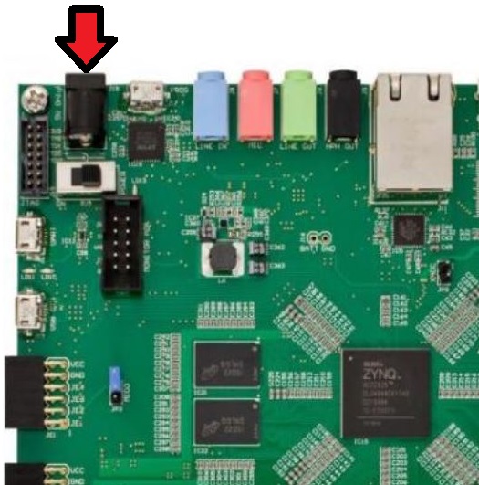
Interfaced with EVAL-CN0363-PMDZ is an FPGA development board (ZED Board rev C or later). Zedboard requires a separate 12V DC power supply connected to its DC power jack.
IOVDD Provisions
EVAL-CN0363-PMDZ provides two options of IOVDD using header JP1. If pin 1 and pin 2 are shorted, IOVDD comes from the regulated supply of the board. If pin 2 and pin 3 are shorted, IOVDD comes from the PMOD interface.
Input Interface
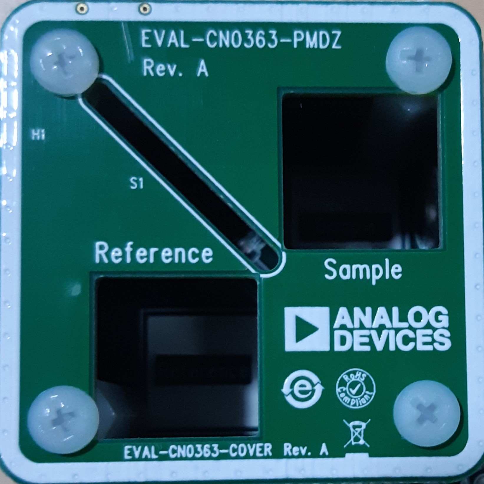
EVAL-CN0363-PMDZ is designed to accommodate two vials. One is for the reference container and the other is for the sample container. A beamsplitter is used to provide similar light source to both vials. The system requires an initial calibration to compensate for misalignment between the LEDs, beamsplitter, and photodiodes, as well as to compensate for any mismatch in the response of the photodiodes.
Vial Holder
The beam-splitter, reference vial, and sample vial are held in a mechanical holder specifically designed for 18 mm x 30 mm plate beamsplitter. Slots are provided to hold the reference vial filled with distilled water and sample vial filled with the test liquid.
Vials and Beamsplitter
Vials that can fit inside a 1 inch x 1 inch slot can be used with EVAL-CN0363-PMDZ. A proper vial preparation is needed to minimize the error acquired in the colorimeter application.
Cleaning Procedure
To obtain the most accurate results when taking measurements, the process below should be taken into consideration:
The vials and beamsplitter must be meticulously cleaned.
Wash the vials and beamsplitter with soap and deionized water.
Soak the vials and beamsplitter in Hydrochloric Acid solution.
Rinse with ultra-filtered deionized water.
Polish with silicone oil.
Calibration Solution
For optimum performance it is necessary to calibrate the application to the connected board and the environment. This calibration can be performed in the calibration dialog which can be opened from the application’s menu. Calibration must be performed with distilled water in both the reference and the sample probes.
Digital Interface
The PMOD interface is a series of standardized digital interfaces for various digital communication protocols such as SPI, I2C, and UART. These interface types were standardized by Digilent, which is now a division of National Instruments. Complete details on the PMOD specification can be found at Digilent Pmod Interface Specification.
The specific interface used for the EVAL-CN0363-PMDZ boards is the extended SPI. In general ADI has adopted the extended SPI connector for all PMOD devices which have an SPI interface. It provides flexibility to add interrupts, general purpose I/O, resets, and other important digitally controlled functions.
Pin Number |
Pin Function |
Mnemonic |
|---|---|---|
P.1 |
Chip Select |
AD_CS |
P.2 |
Gain Control-Reference |
GAIN0 |
P.3 |
Data In |
AD_DIN |
P.4 |
Gain Control-Sample |
GAIN1 |
P.5 |
Data Out |
AD_DOUT |
P.6 |
LED Select |
DA_CS |
P.7 |
Serial Clock |
AD_CLK |
P.8 |
LED Clock |
LED_CLK |
P.9 |
Digital Ground |
GND |
P.10 |
Digital Ground |
GND |
P.11 |
Digital Power |
VCC |
P.12 |
Digital Power |
VCC |
Schematic, PCB Layout, Bill of Materials
Download
The complete design support package containing schematic, assembly drawing, layout files, Gerber files, and bill-of-materials is available at the CN0363 DesignSupport.
Schematics
PCB Layout
Bill of Materials
Software guide
The primary program to interact with the EVAL-CN0363-PMDZ is the ADI Colorimeter application. It can be used to gather, manage and compare processed sample data from the EVAL-CN0363-PMDZ.
Since the Linux drivers used for the EVAL-CN0363-PMDZ use the IIO framework it is possible to use the IIO-Scope to access the raw sample data from the EVAL-CN0363-PMDZ. This is mainly intended to be used for debugging purposes.
All applications run directly on the ZED board itself.