AD9371/AD9375 Advanced Plugin
The AD9371/AD9375 Advanced plugin works with the IIO Oscilloscope. You should always use the latest version if possible. Changing any field will immediately write changes which have been made to the AD9371 settings to the driver, but not to the HW unless the Save Settings button is pressed.
The AD9371 Advanced Plugin allows testing of different device driver initialization options and values. In contrast to the controls on the AD9371/AD9375 Main Plugin - the controls here are not part of the main driver API.
In the No-OS driver the values directly correspond to members of the (mykonosDevice_t) mykDevice init structure. For the AD9371 Linux Device Driver each control corresponds to a specific devicetree property. Since the AD9371 Linux driver uses the Analog Devices provided API driver. Ultimately also for the Linux driver maps any settings back to the mykDevice init structure. It’s therefore recommended to consult the AD9371 User Guide for more information about the options provided here.
See more details about AD9371/AD9375 Customization.
In order for the settings made on this plugin to take effect, the Save Settings button must be pressed. It should be noted that the driver then reinitializes the AD9371 from reset, which will rerun all calibrations and this may take several seconds to complete.
Tip
After you customized the driver for your application needs you can read back all values from the Linux debugfs:
root@analog:/sys/bus/iio/devices/iio:device3# cd /sys/kernel/debug/iio/iio\:device3
root@analog:/sys/kernel/debug/iio/iio:device3# grep "" * | sed "s/:/ = </g" | awk '{print $0">;"}'
adi,clocks-clk-pll-hs-div = <4>; adi,clocks-clk-pll-vco-div = <2>; adi,clocks-clk-pll-vco-freq_khz = <9830400>; adi,clocks-device-clock_khz = <122880>; adi,default-initial-calibrations-mask = <32255>; adi,gpio-3v3-oe-mask = <0>; adi,gpio-3v3-src-ctrl11_8 = <3>; adi,gpio-3v3-src-ctrl3_0 = <3>; adi,gpio-3v3-src-ctrl7_4 = <3>; adi,gpio-oe-mask = <0>; adi,gpio-src-ctrl11_8 = <0>; adi,gpio-src-ctrl15_12 = <0>; adi,gpio-src-ctrl18_16 = <0>; adi,gpio-src-ctrl3_0 = <0>; adi,gpio-src-ctrl7_4 = <0>;[ -- snip -- ]
Simply update the values here: AD9371 Devicetree Initialization
For the No-OS driver the mapping can be found here: AD9371 Customization
Screenshots / Descriptions
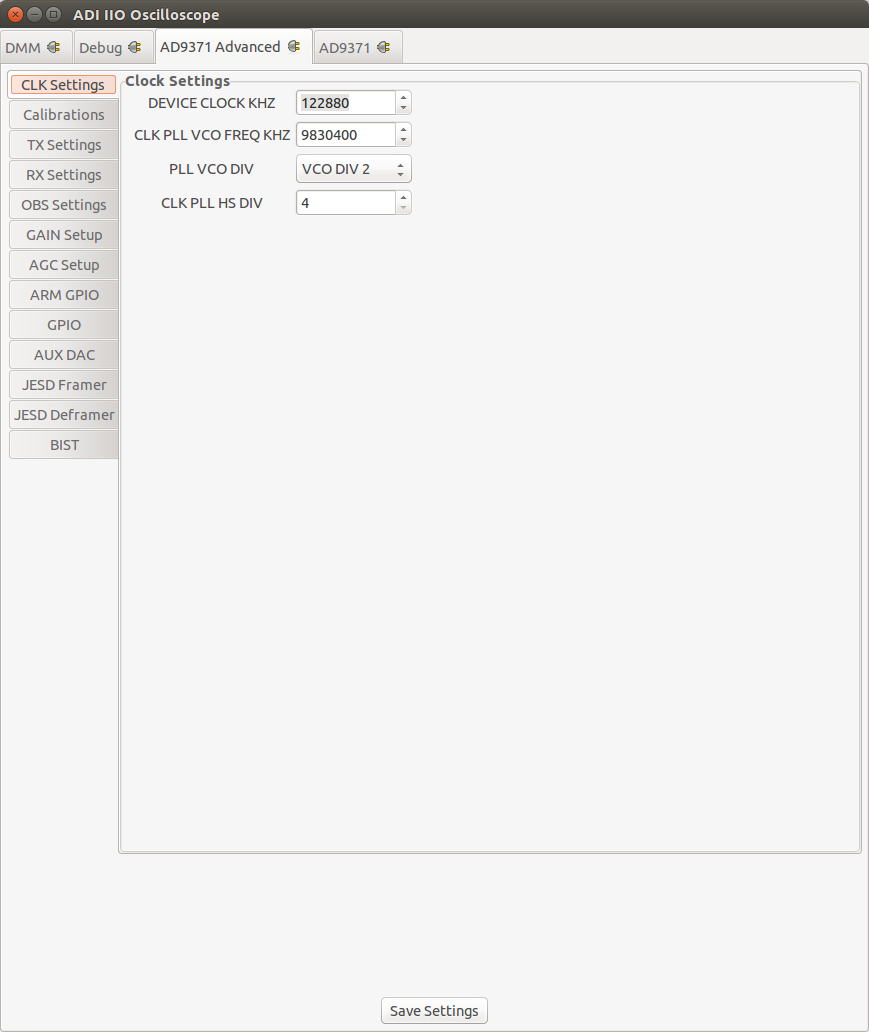
Clock Settings
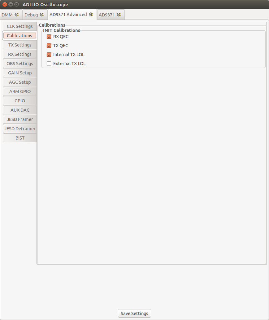
Calibrations
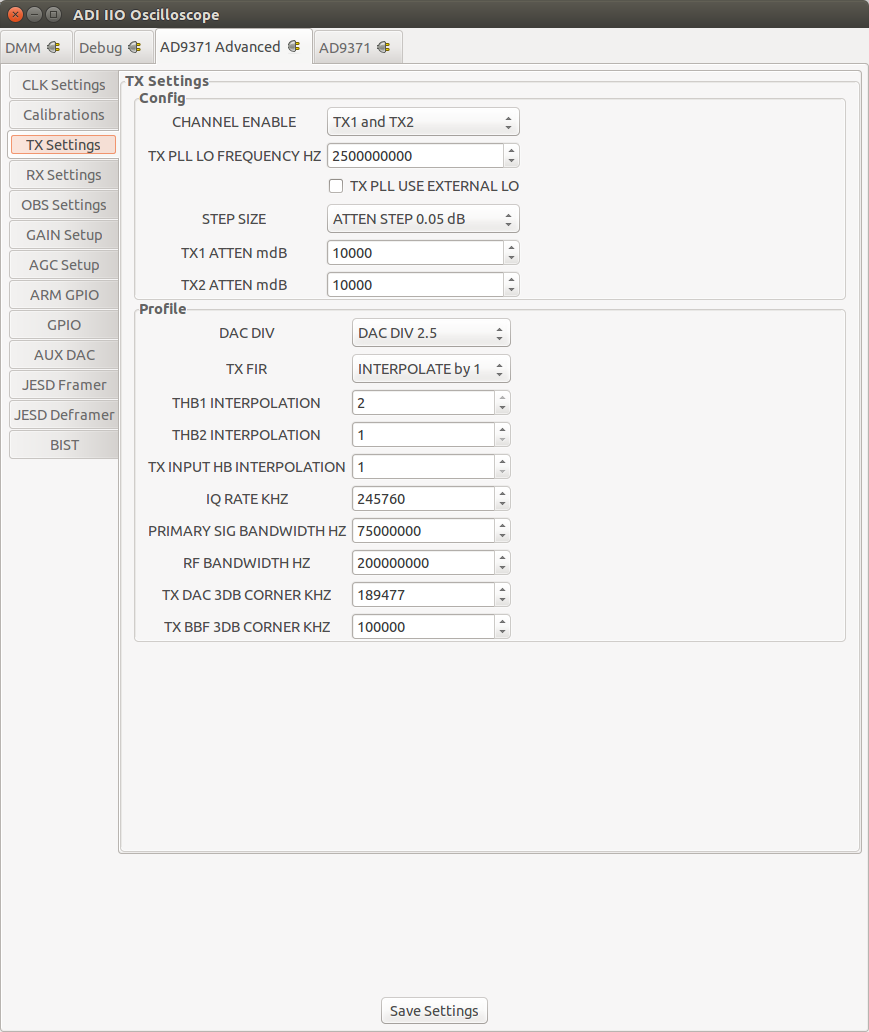
TX Settings
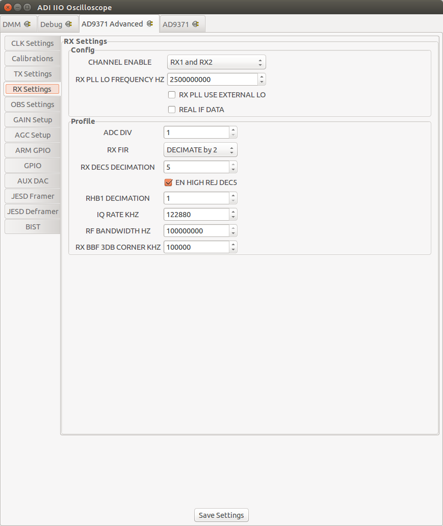
RX Settings
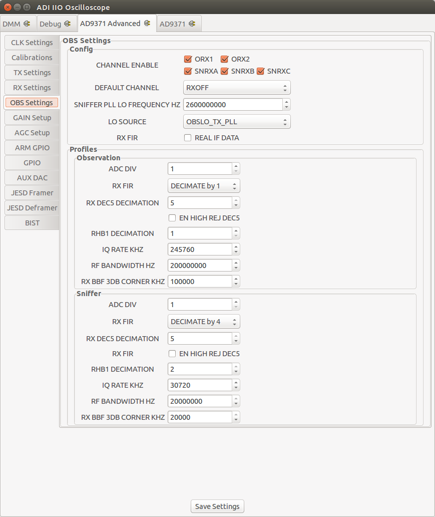
Observation RX Settings
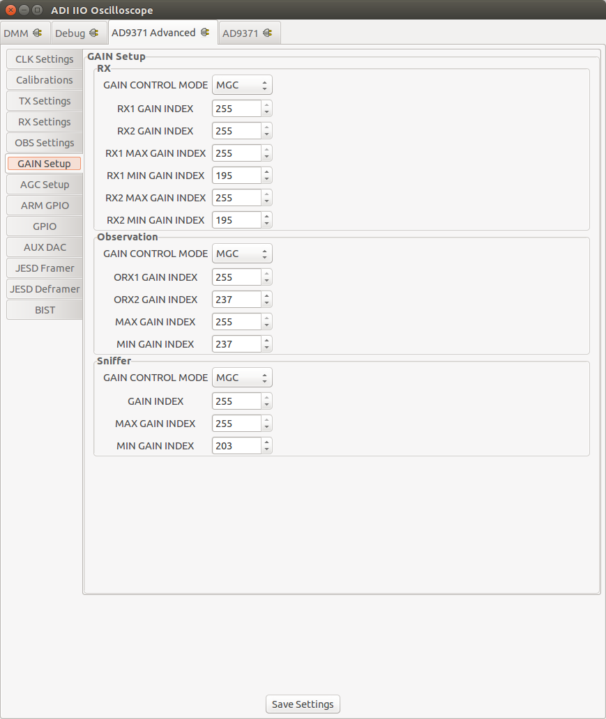
Gain Settings
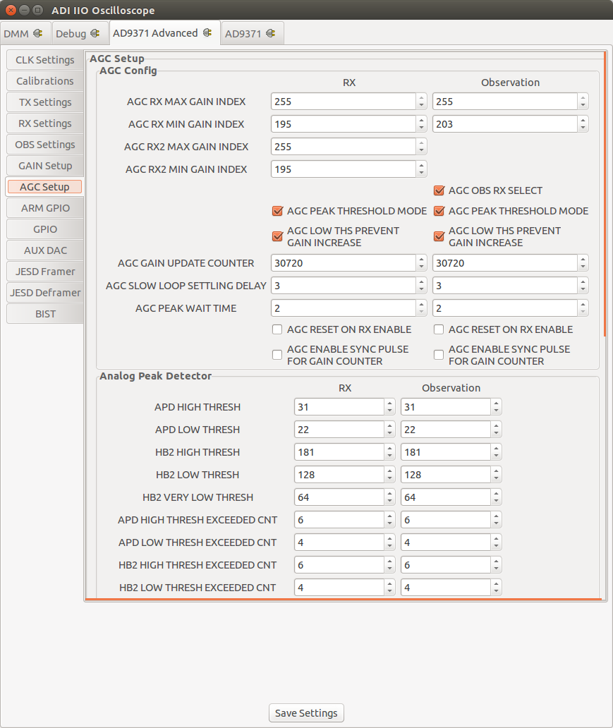
AGC Settings
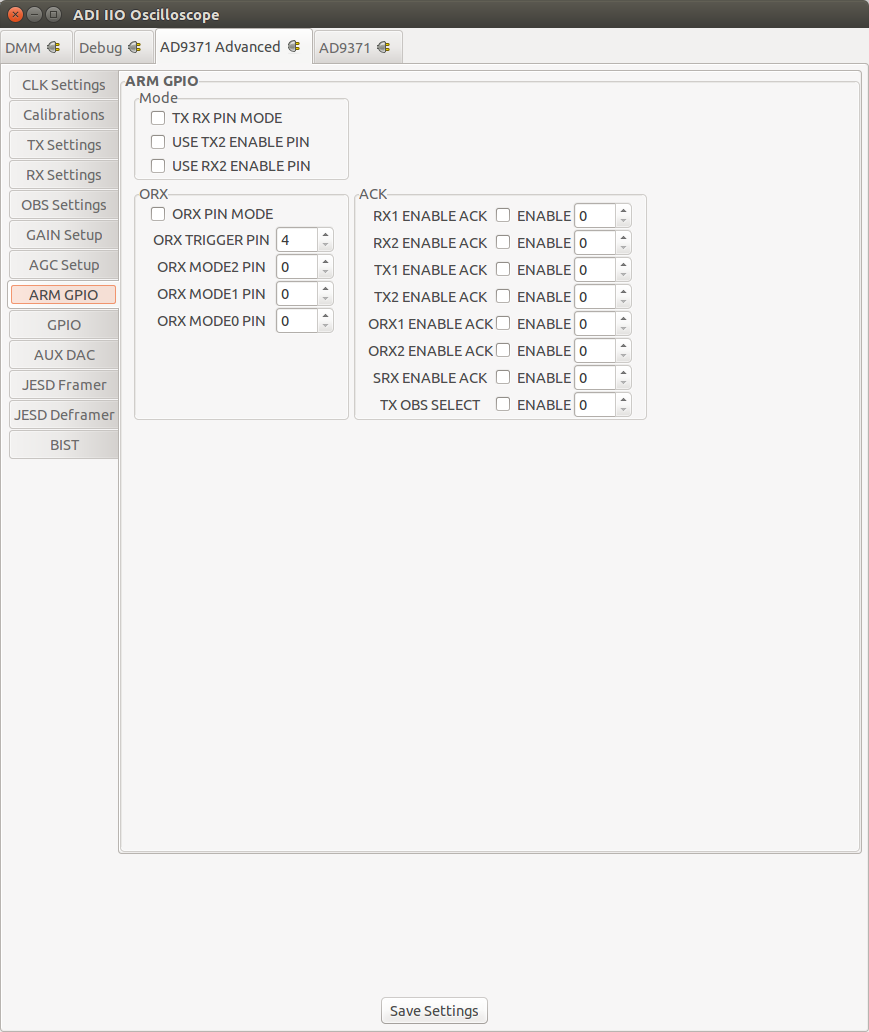
ARM GPIO Settings
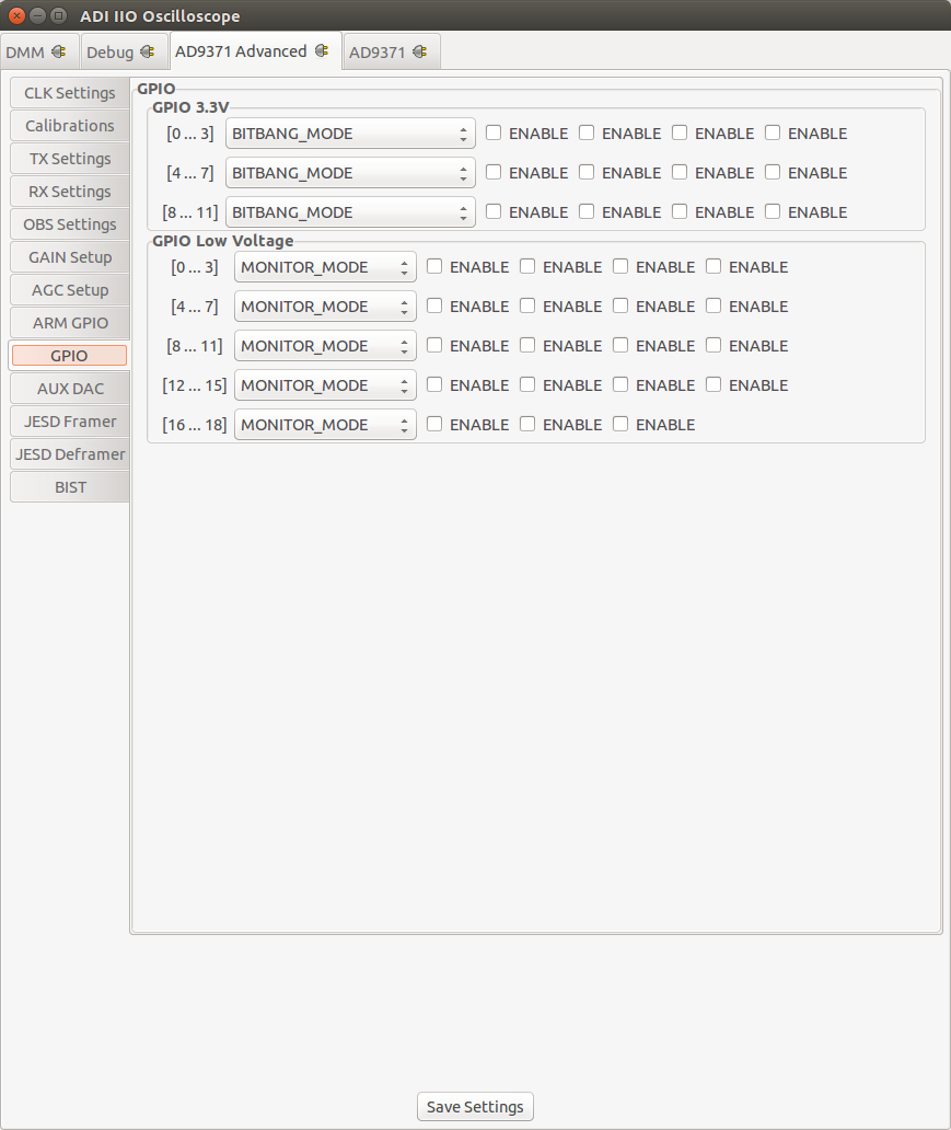
GPIO Settings
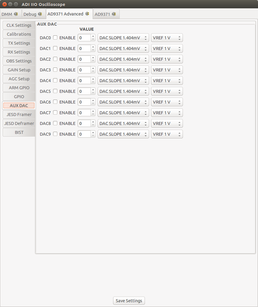
AUX DAC Settings
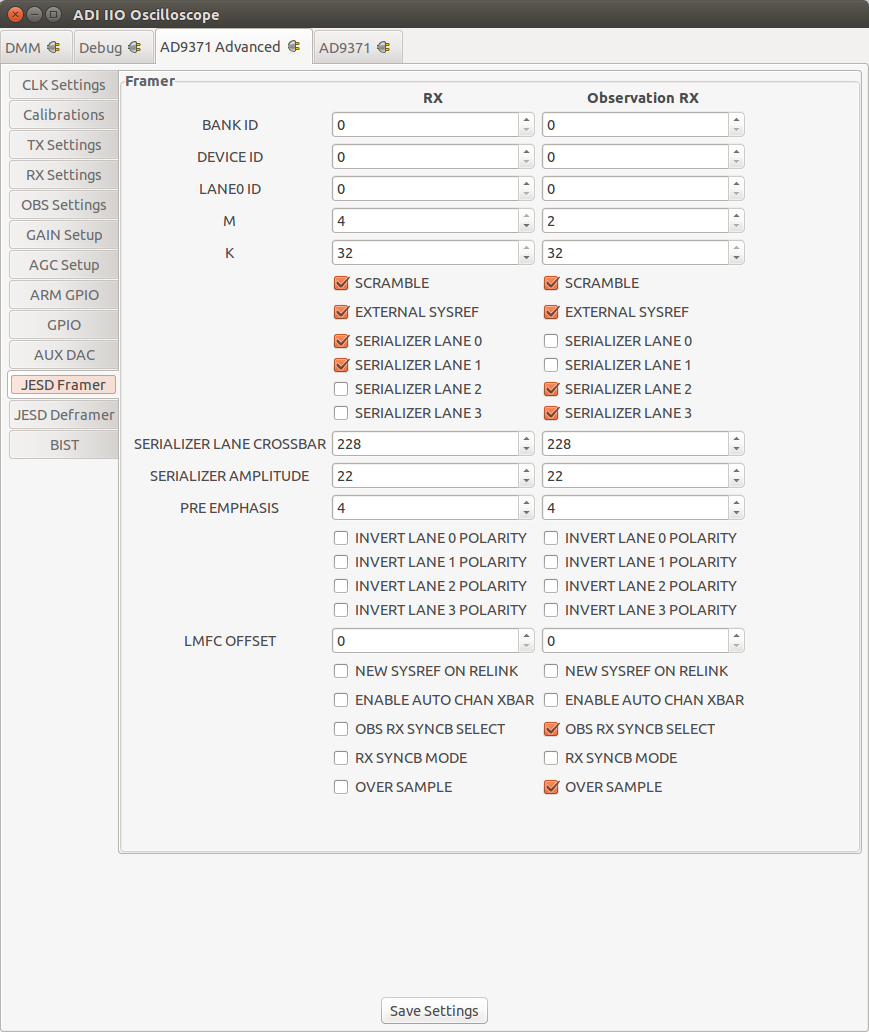
JESD204B Framer Settings
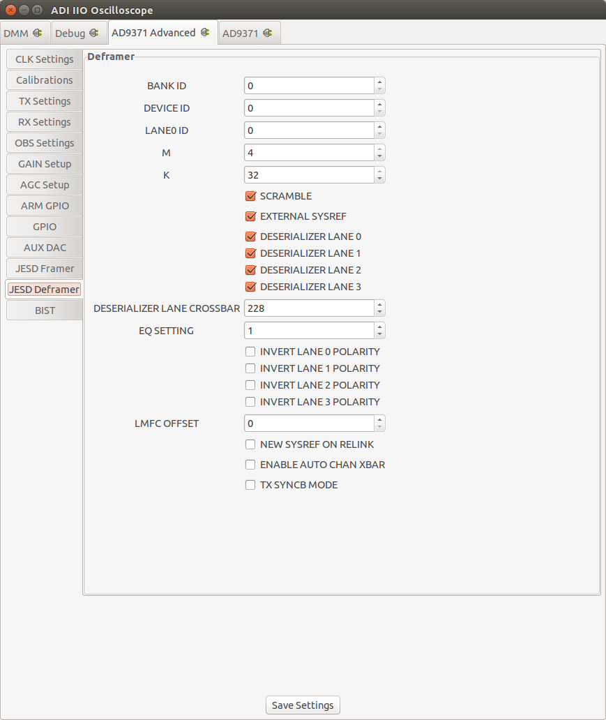
JESD204B Deframer Settings
BIST
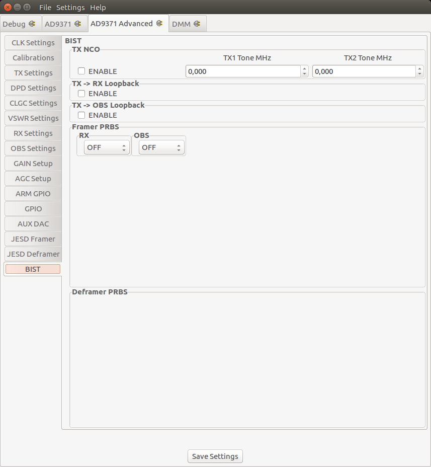
BIST stands for Build-In Self-Test. Selections on this Tab take immediately effect and therefore don’t require the Save Settings Button. Functionality exposed here is only meant to inject test patterns/data than can be used to validate the Digital Interface or functionality of the device.
There are three major facilities:
BIST Tone: User selectable tone with frequency in kHz, that can be injected into the TX path.
BIST PRBS: Pseudorandom Binary Sequence (PRBS) that can either injected into the RX or TX path.
BIST Loopback: Allows to digitally loopback TX data into the RX path.
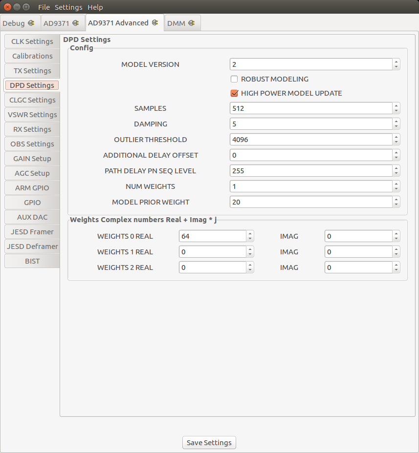
DPD Setup (AD9375 only)
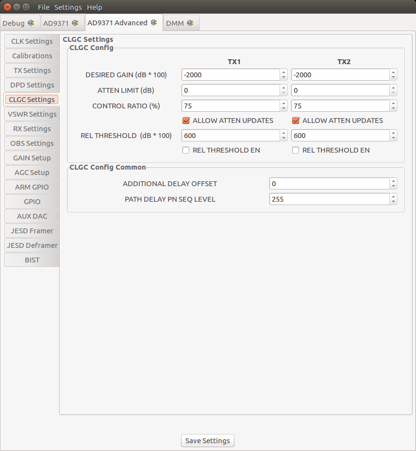
CLGC Setup (AD9375 only)
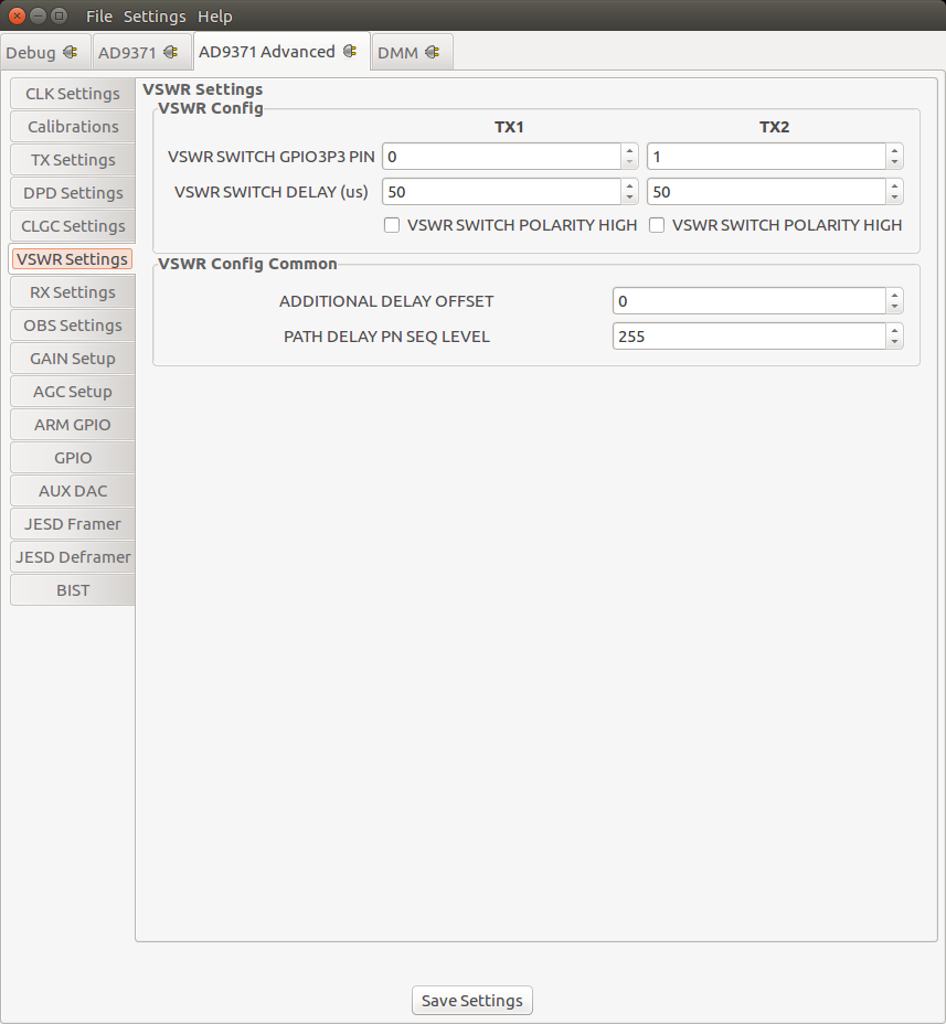
VSWR Setup (AD9375 only)