EVALUATING ADRV904x DPD
CONFIGURING THE ADRV904x TRANSCEIVER
Review the ADRV904X Unboxing and Evaluation Guide. Ensure that the ADRV904x evaluation platform is functional and you are able to interact with the ADRV904x transceiver through the ADRV904x Transceiver Evaluation GUI.
Connect various hardware components of the DPD evaluation system as shown in the Pre-Requisites Page. Leave the Power Amplifiers in the external path turned off at this stage.
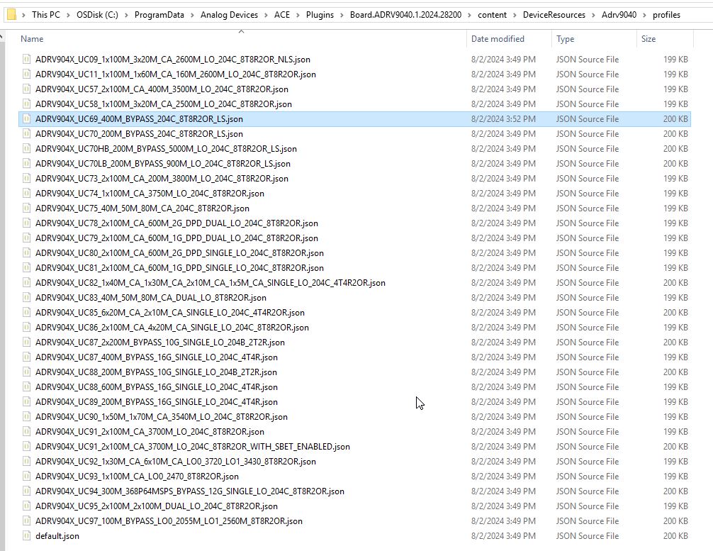
We plan to evaluate DPD in FDD mode using UC69 for this example. The profile UC69 runs DPD actuator at 2GHz rate and the on-chip up-converters(CDUC/BDUC) are bypassed for simplicity. By default, the profiles are configured to run DPD in TDD mode. We must modify the profile json located at “C:/ProgramData/Analog Devices/ACE/Plugins/Board.ADRV9040.<ACE Version>/content/DeviceResources/Adrv9040/profiles” to run DPD in FDD mode. The location for SW 2.12.0.13 is shown in the link below
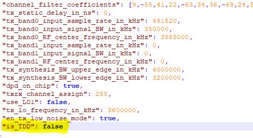
Locate the “is_TDD” in the profile json file at the location shown above and set the value of “is_TDD” setting to “false” as highlighted below to enable DPD to run in FDD mode. There are a total of 4 “is_TDD” switches in the profile json where this modification needs to be made.
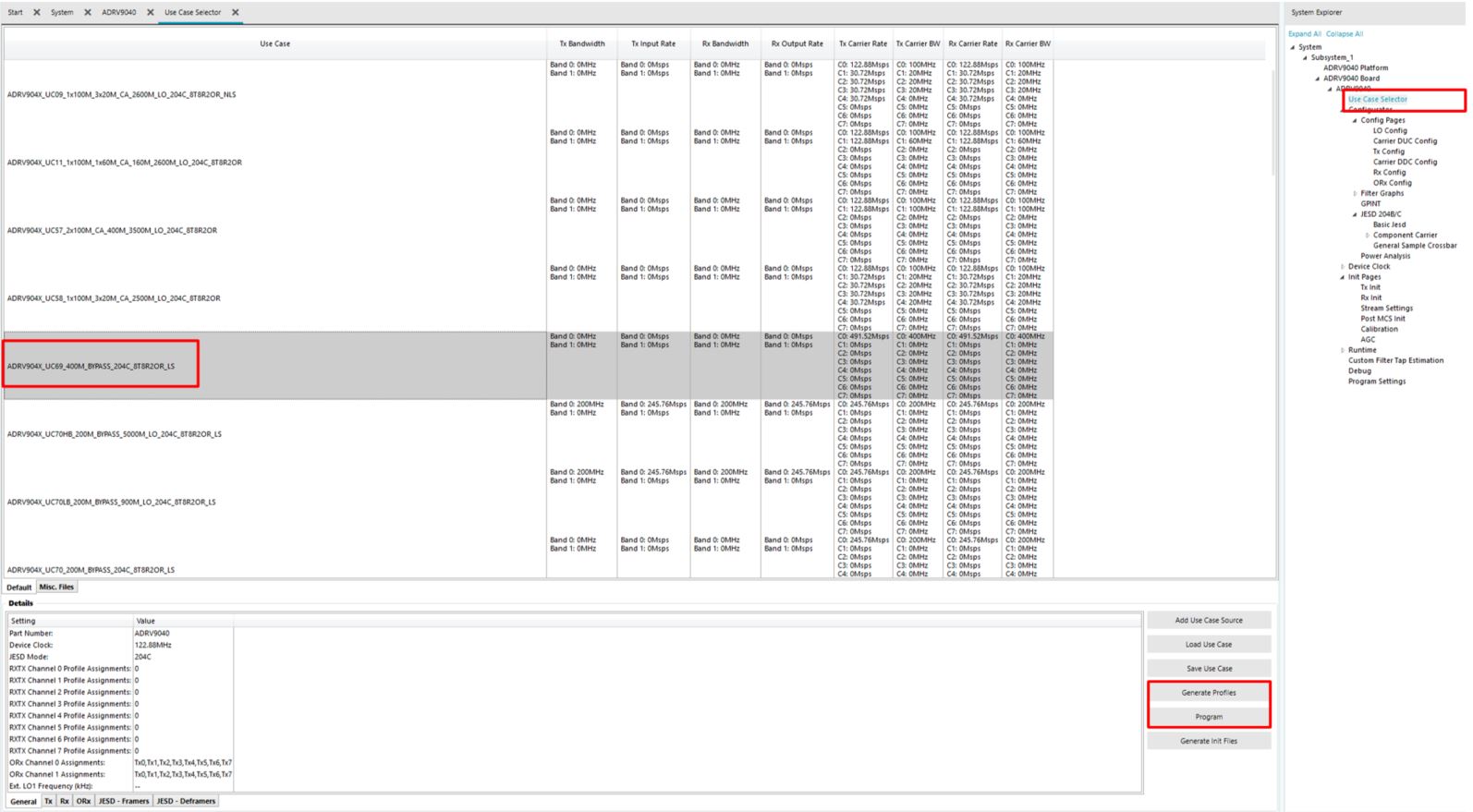
Now, we proceed to programming ADRV904x with the profile UC69. Browse to the “Use Case Selector” page under ADRV9040 system explorer. Select the profile “ADRV904x_UC69_400M_BYPASS_204C_8T8R2OR_LS” as highlighted in the picture below. Click the “Generate Profiles” button followed by the “Program” button encircled in the picture below. On successful programming of the device, proceed to next step. Review the ADRV904X Unboxing and Evaluation Guide in case of errors
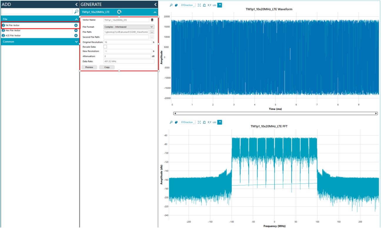
We can proceed to transmit the waveform now. Browse to the Tx Vectors page under ADRV9040->Runtime labeled 1 in the picture below. Ensure that TDD State Machine Enable is unchecked as shown in box labeled 2 in the picture below. Ensure that Tx Mode Select is set to SPI and Tx Trigger is set to Immediate Trigger as shown in box 3. We can proceed to load a waveform by clicking the Vectors button labeled 4 in the picture below.

The Vectors tab enables the user to load a custom waveform as shown in the picture below. In this example, a 10x20MHz LTE signal sampled at 491.52MSPS matching the Tx rate of UC69 is loaded.
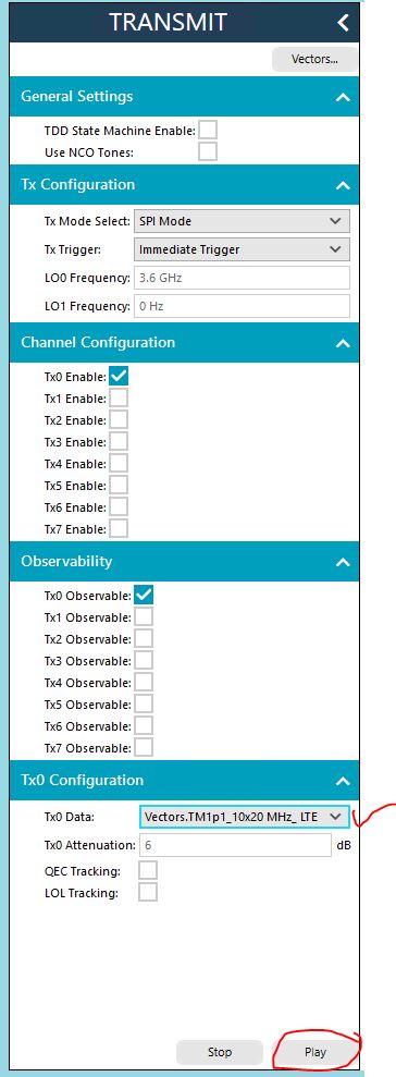
We can now proceed to transmit the vector through the following steps
Check the correct Enable box corresponding to the Tx channel used. In this example, we use Tx0
Check the Observable button corresponding to the Tx channel used for testing. In this example, we map Tx0 to ORx0.
Select the appropriate waveform from the drop down list. Select the optimum attenuation and click on the “Play” button encircled below to play the waveform out of Koror. Please note that it can take several seconds to load the waveform on ADS10 and play the waveform. At this stage the external power amplifiers can be turned on to observe the spectral output
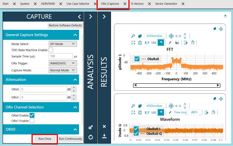
The user can now proceed to check the transmit output on the spectrum analyzer and calibrate the output of the power amplifier. Additionally, the user can verify the ORx data looks correct by capturing data on the ORx data as shown in the picture below.
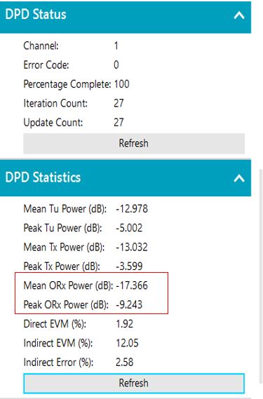
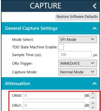
NOTE: Please ensure that ORx peak power doesn’t exceed -6dBFS (normalized peak magnitude of 0.5) to prevent ADC saturation. Since Koror uses direct sampling ADC on ORx, the signal + image power at ADC is 6dB higher than what the DPD sees.
The ORx attenuation can be adjusted to optimum levels through the encircled ORx attenuation section in the ORx capture page
Once the Transmit path and observation path signal levels have been calibrated, now we can proceed to configuring the DPD through the following steps
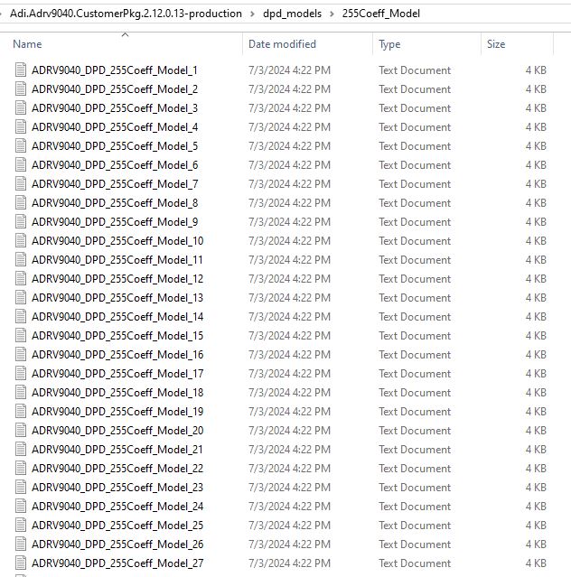
ADI releases DPD Model Libraries as part of the ADRV904x SW package shown in the picture below. We can pick any DPD model from the library for simplicity. DPD Model optimization will be covered in the next few sections
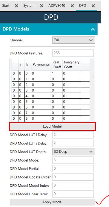
Load the DPD Model and click the Apply button as shown in the picture below under the ADRV9040->DPD tab. All the parameters must be populated automatically from the DPD model text file, if it is loaded successfully.
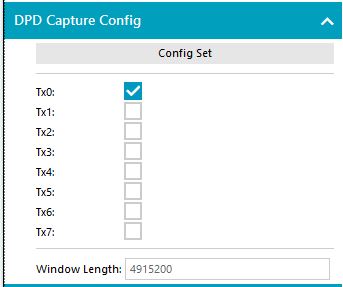
The DPD capture configuration can be setup to search for the highest peak in a 10ms search window by setting the “Window Length” to 4915200 samples at 983.040 MHz capture rate for this profile. There is an internal multiplication factor of 2x for the window length. Therefore, we set the window length to be equal to 983400 divided by 2 for a total of 10ms.
Setup the DPD tracking configuration as shown in the picture below. Apply the configuration by clicking on the “Apply Tracking Config” button. Click the “Reset DPD” button to reset DPD to a known good state and then enable DPD tracking calibration by clicking on the “Enable DPD Tracking Cal” button.
![]()
At this point we must see the ACLR converge on the spectrum analyzer and also see the DPD update count continuously incrementing.