Beamforming Theory
Before implementing beamforming with the PlutoSDR, let’s briefly review the physical and mathematical principles that make it possible.
Basic Concept
Beamforming is a signal processing technique used in antenna arrays to direct the reception or transmission of signals in specific directions. By adjusting the phase and amplitude of the signals at each antenna element, we can create constructive interference in the desired direction and destructive interference elsewhere.

Basic Beamforming Math
If an RF signal arrives at a phased array from an angle away from mechanical bore-sight, the wavefront reaches each element at slightly different times.
These received signals are phase-shifted versions of the same waveform. To achieve coherent summation (constructive interference), we must apply an equal and opposite phase shift — effectively “undoing” the delay introduced by the wavefront’s angle of arrival
So, your first step in phased array signal processing is understanding how an element delay translates to a steering angle:
Derivation of the Phase Shift for Beam Steering
Referring to the diagram below, we can derive the relationship between the phase shift required for beam steering and the angle of arrival of the signal.
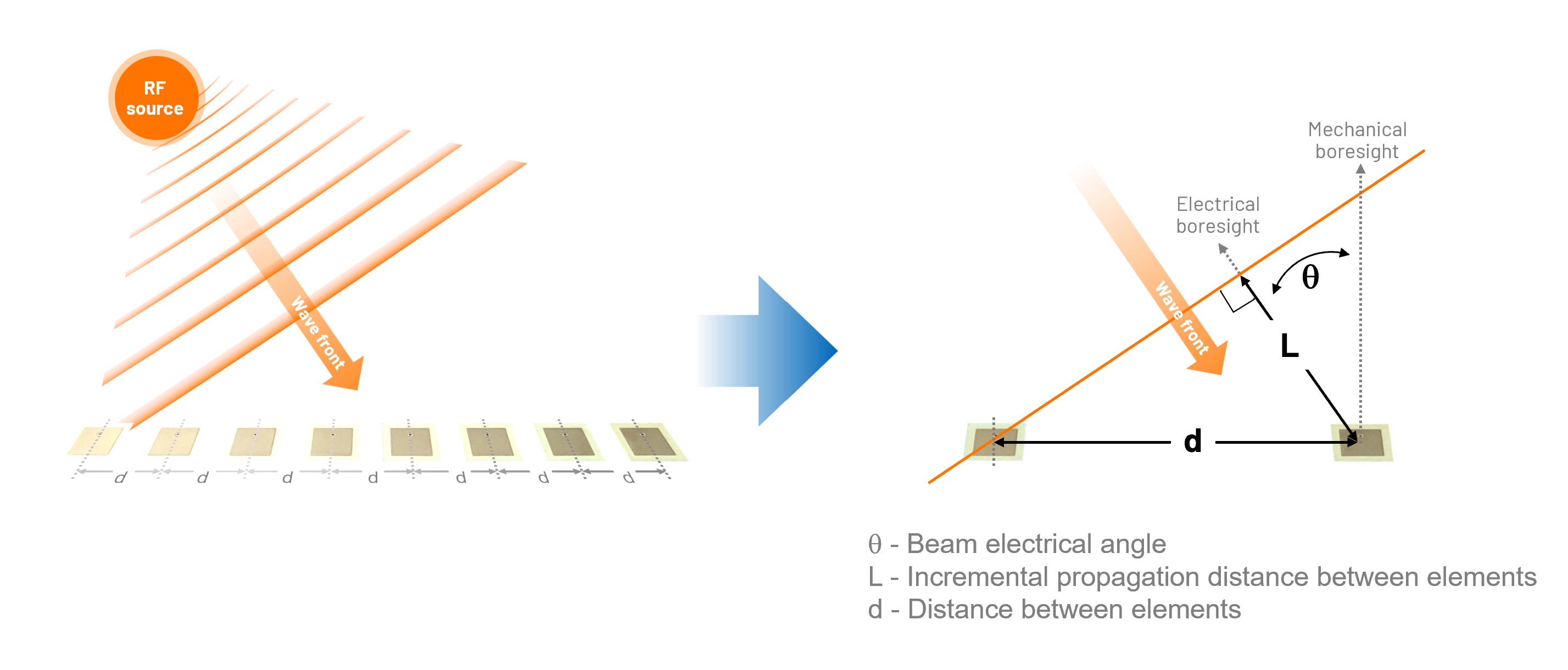
Start with the additional path length L between adjacent elements due to wavefront tilt:
The internal angle of our right angle triangle is 90 - θ. From basic trigonometry we know that:
If we convert to time:
Or in terms of phase:
Thus a time (t) or phase shift (Φ) between each antenna element will steer the beam in the direction of θ.
Array Factor
The array factor (AF) describes the directional response of an antenna array as a function of the angle of arrival (θ) and the phase shift applied to each element. For an N-element array with uniform spacing and phase shifts, the array factor can be expressed as:
For a two-element array, this simplifies to:
How to we use this with Pluto?
As our PlutoSDR has been modified and configured for dual Rx, we can apply the above theory to steer our beam in software by applying the appropriate phase shift to the received signals from each antenna element. By adjusting the phase shift from each channel we create constructive interference in the desired direction or directional gain, and thus beamforming is achieved.
In the next section, we will go through the practical setup and implementation of beamforming with the PlutoSDR, including hardware assembly and software configuration.