Phaser’s Device Tree Overlay
Understanding Phaser’s Device Tree
In a Linux operating system, the “device tree” tells the OS what it is physically connected to. And so, if we’re going to connect hardware (Phaser) to our Linux OS (Raspberry Pi), then we’ll need to tell the device tree what we’re connecting. We wouldn’t want to rewrite the device tree for the entire Linux computer, so instead we just tack on a device tree overlay. The overlay will add our Phaser connections to whatever device tree was already installed. Take a look at Phaser’s device tree overlay here.
If this is your first time seeing a device tree, you may find it a bit difficult to read! There’s a lot of odd syntax in there. But luckily our goal isn’t to write our device tree. We’re just trying to understand what’s there so that we can control it with the IIO software. Therefore, let’s focus on a few key lines to understand the connection between hardware and the IIO software.
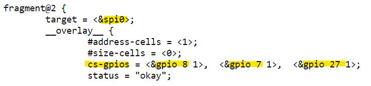
Under a section of code labeled “fragment@2”, you’ll see 3 main sections: adar1000@0, adar1000@1, and adf4159@2. And it seems like these 3 devices are all going to use the Raspberry Pi’s spi0 bus. And have their SPI CS pin controlled by GPIO 8, 7, and 27 (respectively for the 3 devices).
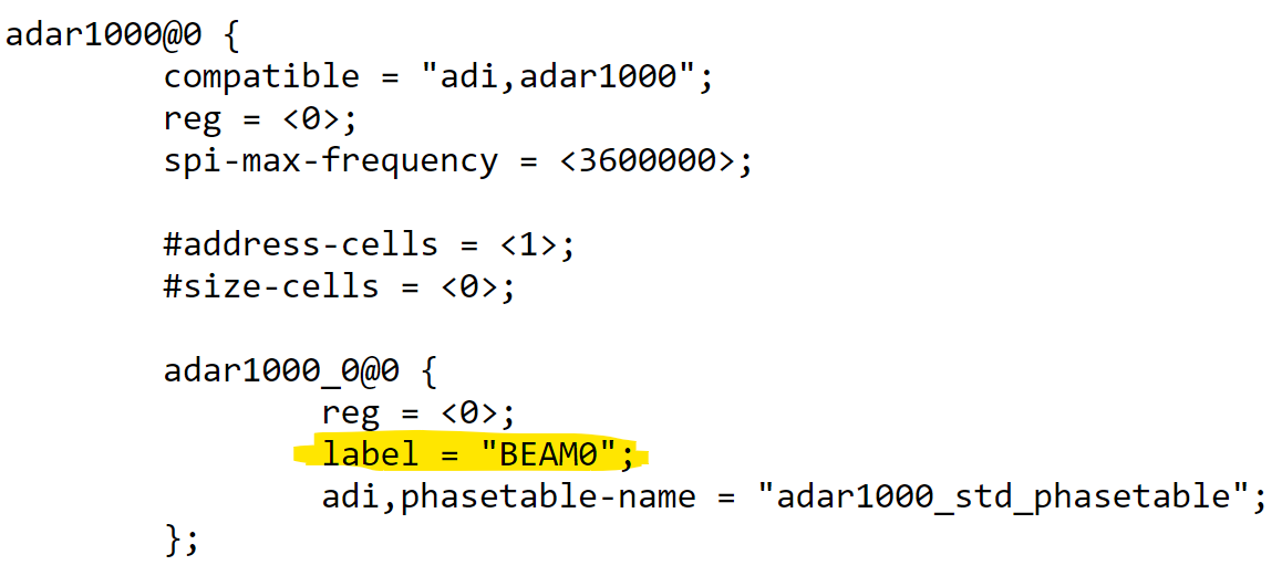
For the two ADAR1000s on Phaser, you’ll see that they have a label “BEAM0” and “BEAM1”. And the ADF4159 is given the label “pll0”. Remember those! We’ll use these labels to tell Python which device we want to control.
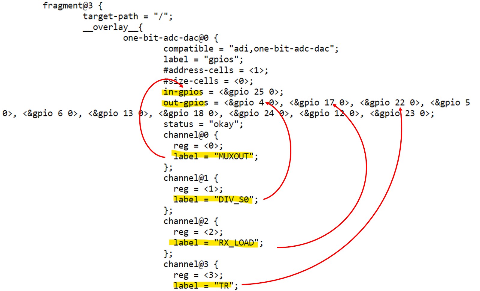
You’ll also see a list of “one-bit-adc-dac” channels. These are GPIOs (general purpose inputs/outputs) on the Raspberry Pi. Each one also has a “label”, and we’ll again use those labels to read or set the voltage on that pin. The actual pins, located on the Raspberry Pi 40 pin header, are given in the list of “in-gpios” (for pins where we read the voltage) and “out-gpios” (for pins where we set the voltage). That might be useful if you want to probe a pin and see if you are setting it correctly.
A Simple Python Beam Steering Program for Phaser
Now let’s look at a simple Python script, and see how IIO makes use of the device tree to control the hardware. You can find an example of beam steering in Python beamsteer.py. Open up “beamsteer.py” and you’ll notice that we map each element of Phaser’s receive array to a specific channel on the two ADAR1000s. Here’s what that looks like:
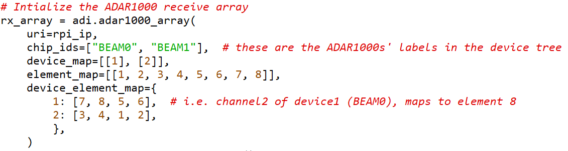
So “rx_array” is an array of 2 ADAR1000s called “BEAM0” and “BEAM1.” The “device_map” sets BEAM0 as device 1, and BEAM1 as device 2. The element map is how we are arranging elements 1 through 8. This is for a linear array, but you could also add another row for a two-dimensional array. The physical arrangement looks like this:
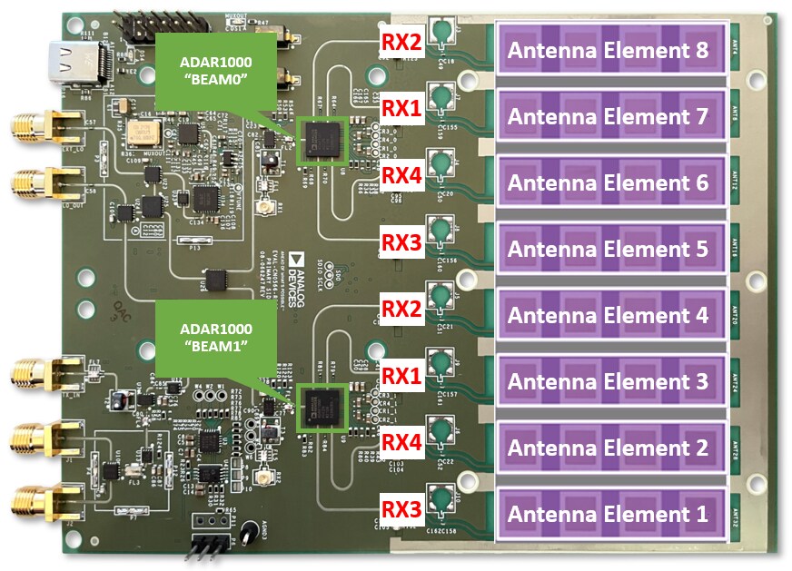
Now we map each of the ADAR1000’s 4 channels to one of those elements. For example, channel 2 (RX2 pin of the ADAR1000) of device 1 (BEAM0) will map to element #8. Or channel 3 of device 2 (BEAM1) maps to element # 1. The great thing about this setup is we never again need to refer to which ADAR1000 we are controlling. We just refer to the antenna element number or the beam output number. This minimizes the changes required to software if you want to build a prototype with more elements or a different arrangement of the elements.
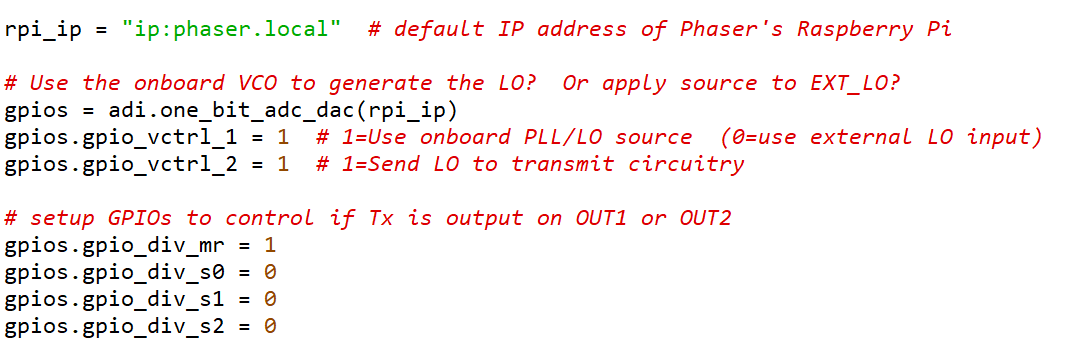
And remember those GPIOs? Here’s a snippet on how we access them to set them high or low:
Note
For questions or help with the Phaser, please visit: EngineerZone