SDP-K1 / Nucleo-L552ZEQ Quick start
All the products described on this page include ESD (electrostatic discharge) sensitive devices. Electrostatic charges as high as 4000V readily accumulate on the human body or test equipment and can discharge without detection. Although the boards feature ESD protection circuitry, permanent damage may occur on devices subjected to high-energy electrostatic discharges. Therefore, proper ESD precautions are recommended to avoid performance degradation or loss of functionality. This includes removing static charge on external equipment, cables, or antennas before connecting to the device.
This guide provides step-by-step instructions on how to set up the EVAL-AD7770-AD7779 with an SDP-K1 or Nucleo-L552ZEQ controller board using the IIO firmware application.
Note
This guide covers the legacy SDP-K1 / Nucleo-L552ZEQ setup using MBED and STM32 firmware via UART. For the recommended Linux-based setup on a ZedBoard, see ZedBoard Quick start.
Overview
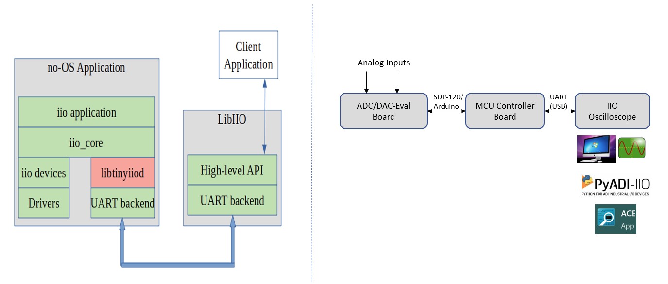
The firmware application leverages the ADI IIO ecosystem to evaluate the AD777x family. It runs on the SDP-K1 (MBED platform) or Nucleo-L552ZEQ (STM32 platform) and communicates with IIO Oscilloscope on the host PC over UART.
Hardware connections
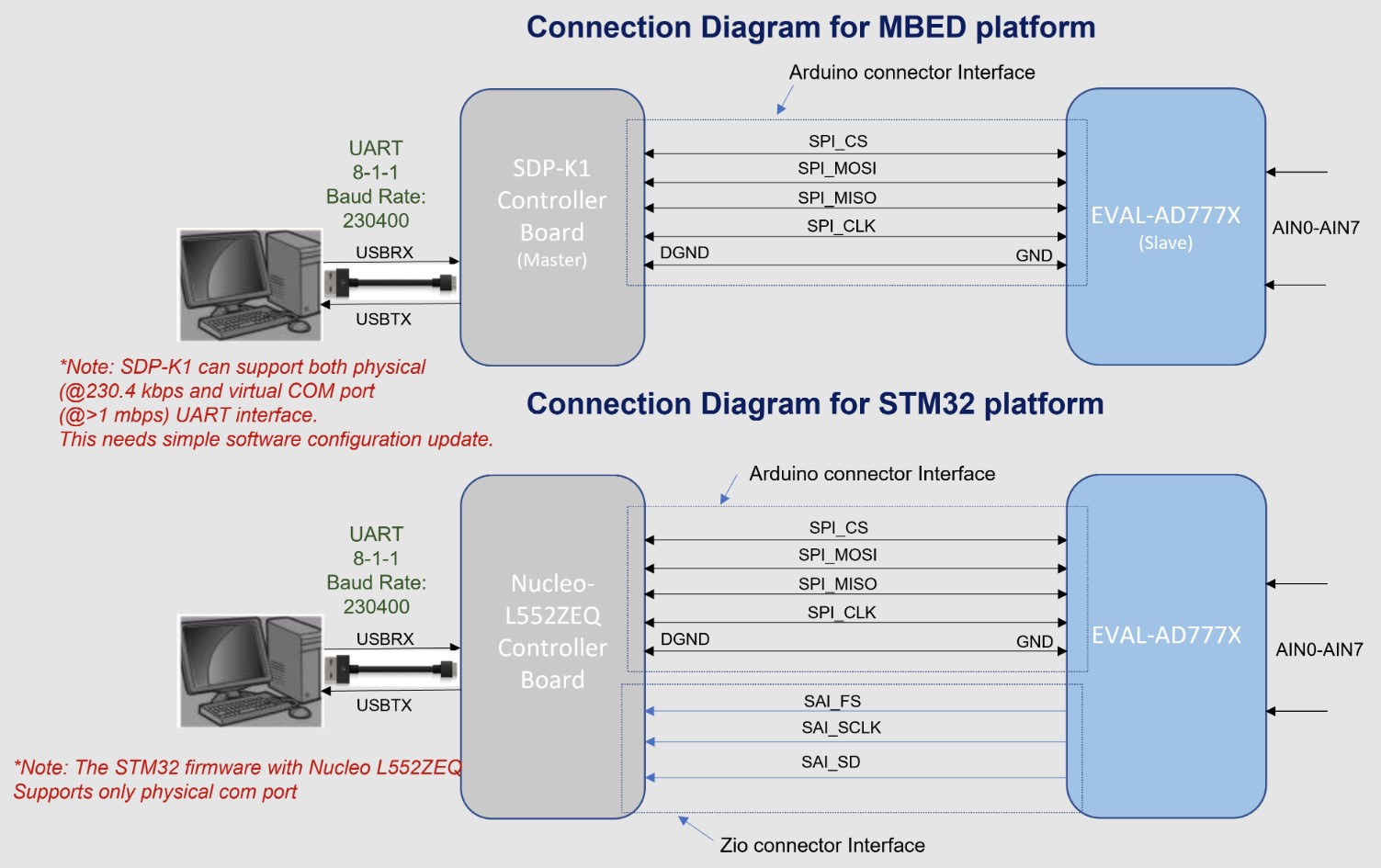
SDP-K1 (MBED platform)
Connect the VIO_ADJUST jumper on the SDP-K1 board to the 3.3V position to drive SDP-K1 GPIOs at 3.3V.
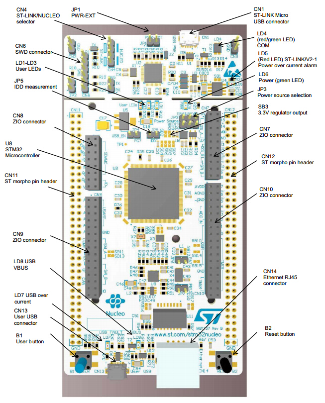
Nucleo-L552ZEQ (STM32 platform)
Refer to the Nucleo-L552ZEQ User Manual for board-level details.
EVAL-AD777x
Refer to the AD777x evaluation board user guide available on the respective device product pages for board-level details.
Firmware
The firmware source code is hosted in the ADI precision-converters-firmware repository repository.
app_config.h
This file is used to configure the firmware:
Select the active device by changing
#define DEV_AD7770(default is AD7770).Select the platform by setting
#define ACTIVE_PLATFORMtoMBED_PLATFORMorSTM32_PLATFORM.Set
DATA_CAPTURE_MODEtoCONTINUOUS_DATA_CAPTUREorBURST_DATA_CAPTURE.Set
INTERFACE_MODEtoSPI_MODEorTDM_MODE.
Important
The maximum output data rate can only be achieved with TDM_MODE
on the STM32 platform. SPI_MODE limits the maximum achievable ODR.
Running IIO Oscilloscope
Open IIO Oscilloscope on the host PC and configure the serial (UART) settings. Click Refresh - the AD777x device should appear in the IIO devices list.
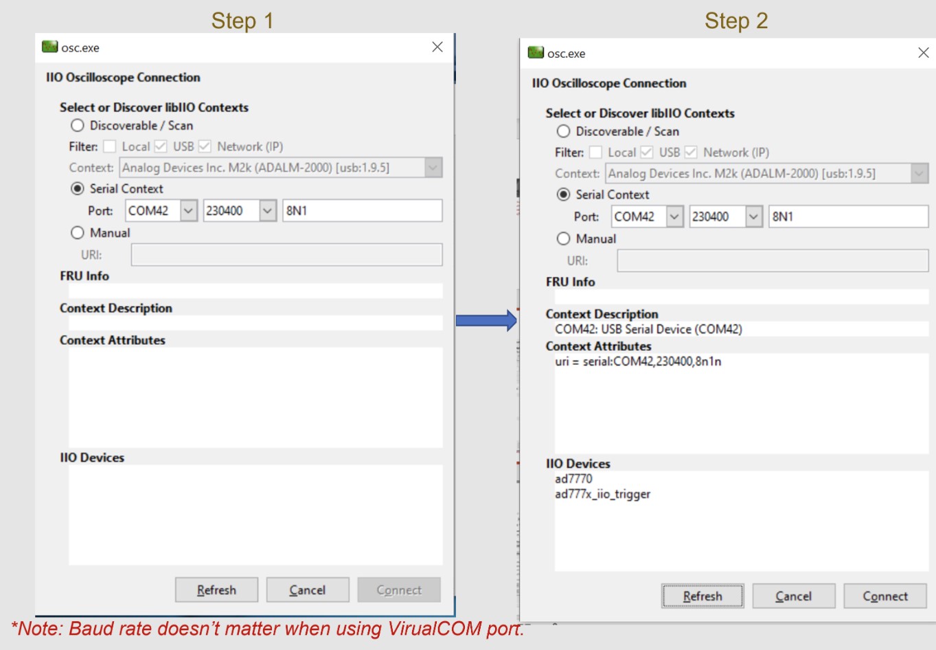
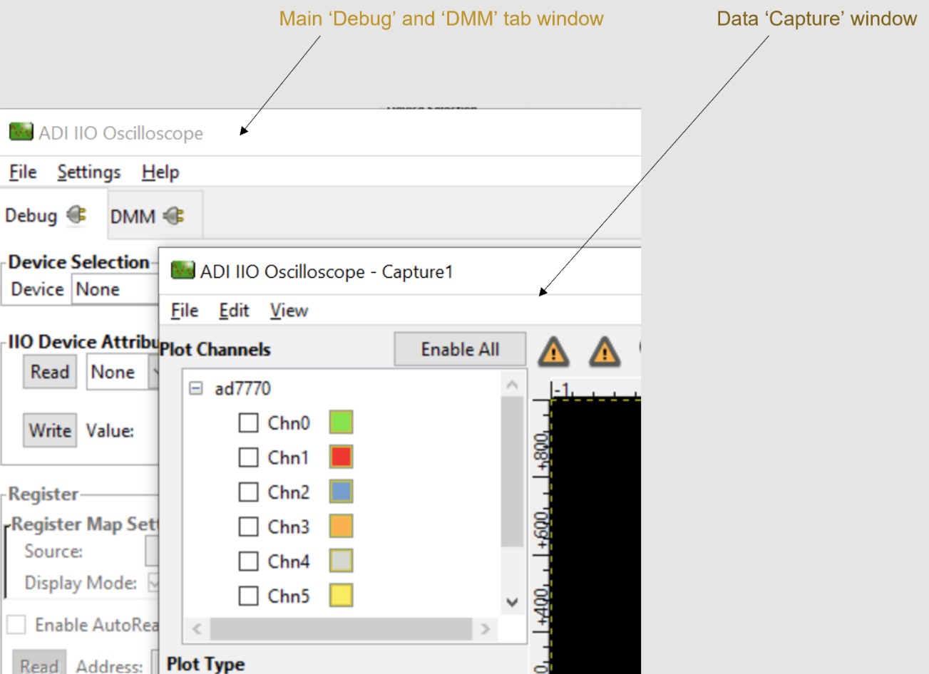
Click Connect. The data Capture window opens by default. You can drag it aside or close it to access the Debug and DMM tab.
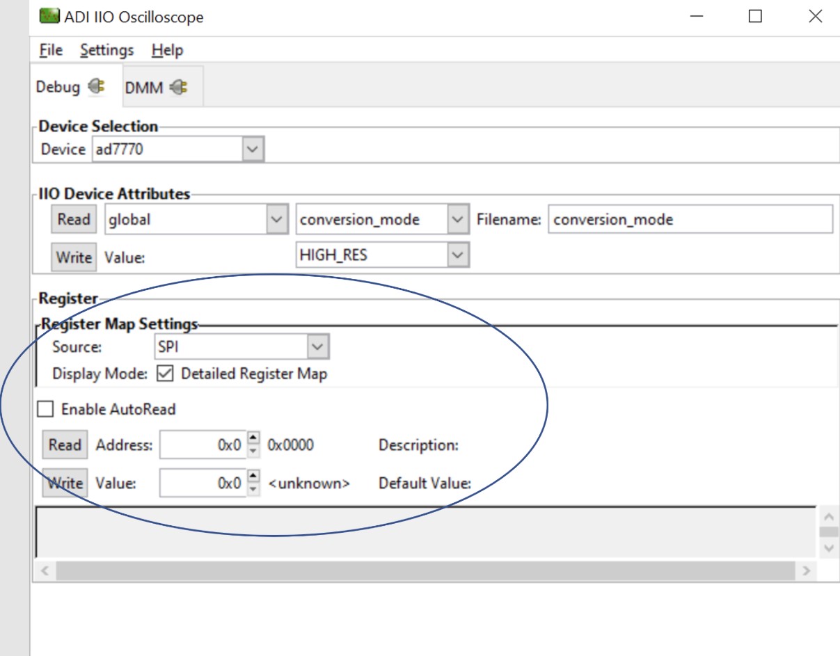
Select the device from the Device list in the Debug tab to access all device and channel attributes.
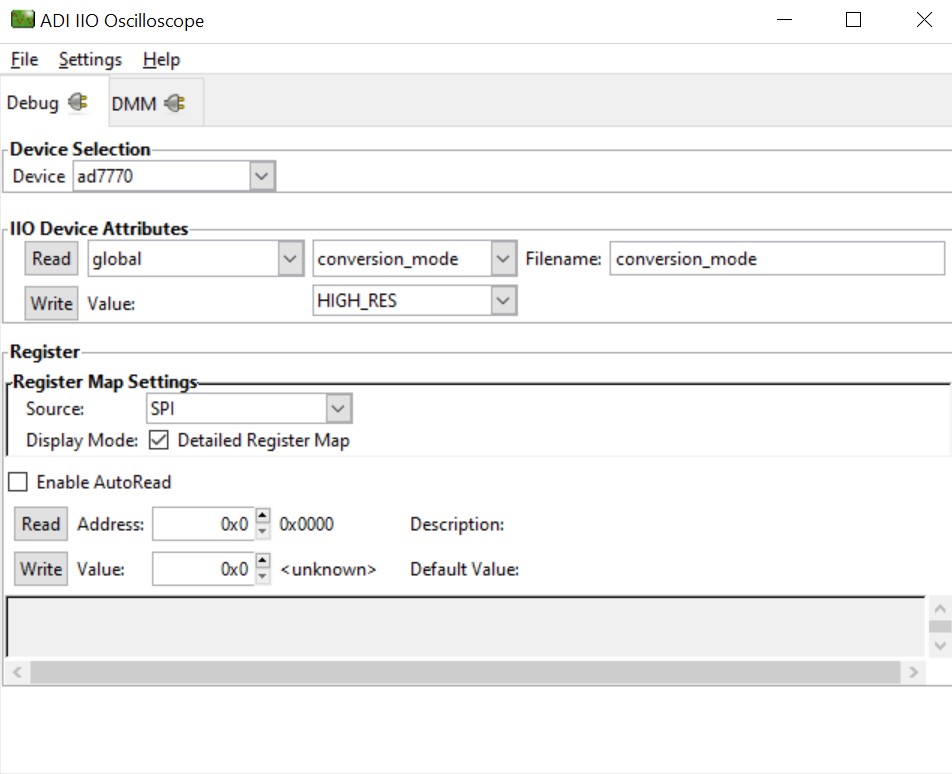
Figure 6 IIO Oscilloscope debug window with AD777x attributes
Device attributes
IIO Oscilloscope exposes two types of attributes:
Device attributes - global parameters common to the device.
Channel attributes - parameters specific to individual channels.
To read an attribute, select it from the list and press Read. To write, set the value in the value field and press Write.
DMM tab
The DMM tab reads the instantaneous voltage on analog input channels. Select the device and channels, then press Start.
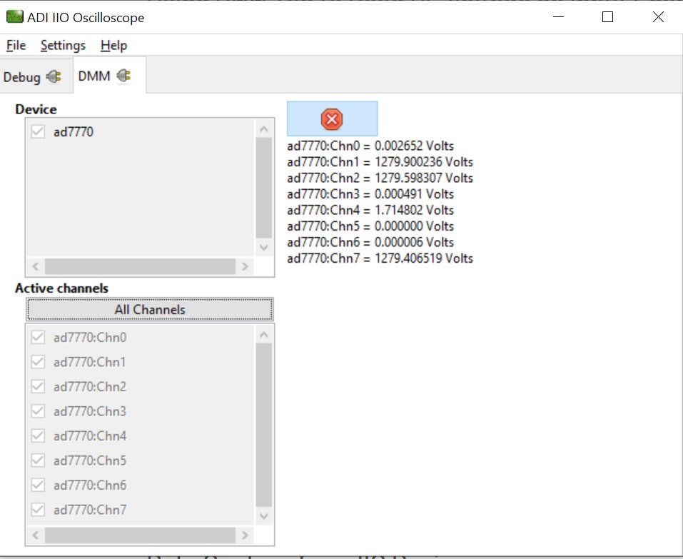
Note
DMM reads instantaneous values only - RMS AC or averaged DC voltage is not available. Do not use the DMM tab simultaneously with the Capture or Debug tab.
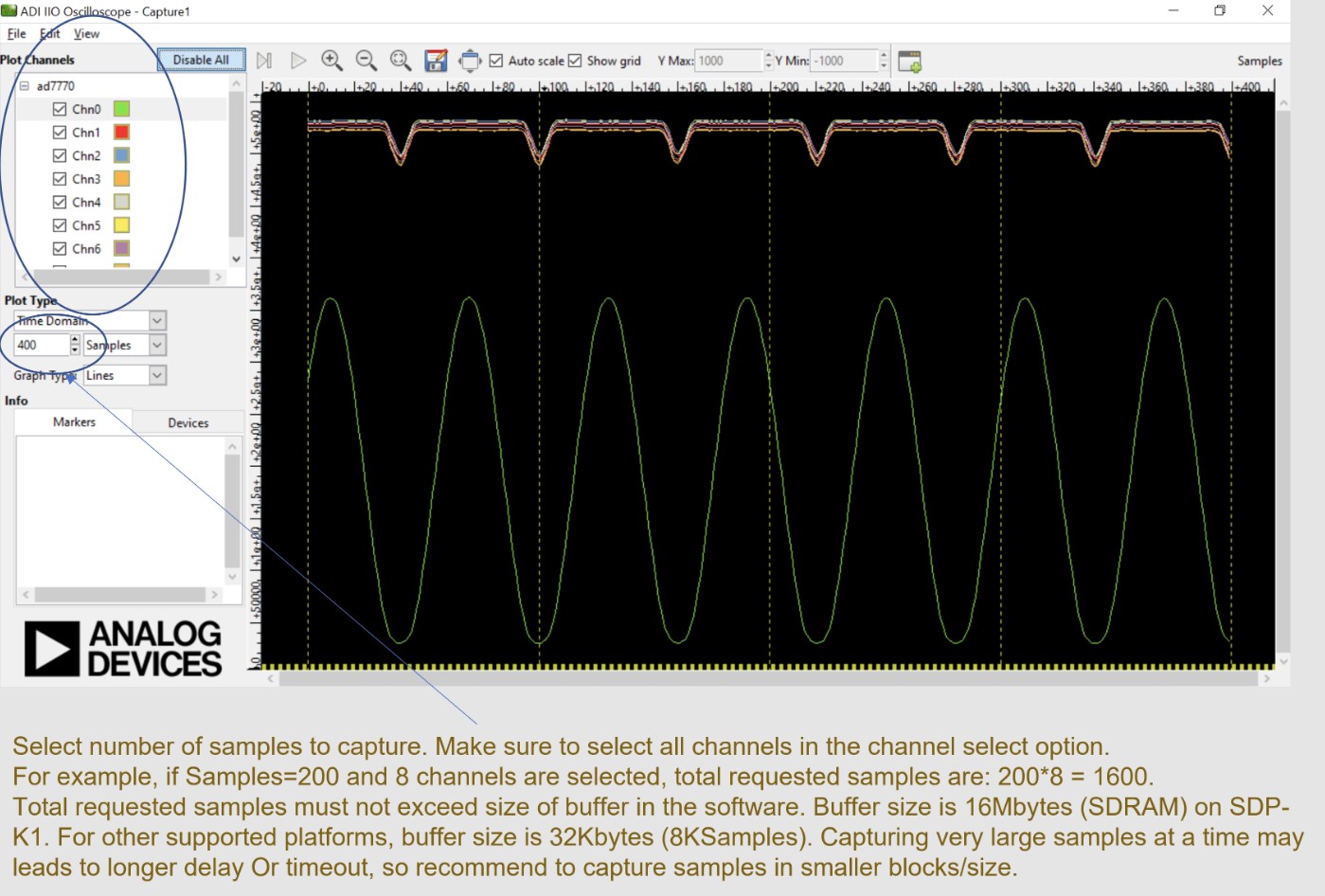
Data capture
Select the device and channels in the Capture window to start data capture. Data is plotted as ADC raw value vs. number of samples.
Warning
Do not access the DMM or Debug tab while capturing data - this impacts capture. DMM uses single conversion; data capture uses continuous conversion mode.
Register map
The Register Map tab provides byte-level access to the device registers.