AD-IMP2501-SL
1 Hz to 1.5 MHz impedance analysis evaluation and technology solution.
Overview
The AD-IMP2501-SL is an impedance analyzer demonstrator and technology evaluation system comprised of both the AD-IMP2501DBZ-SL and the AD-IMP2501EBZ-SL boards.
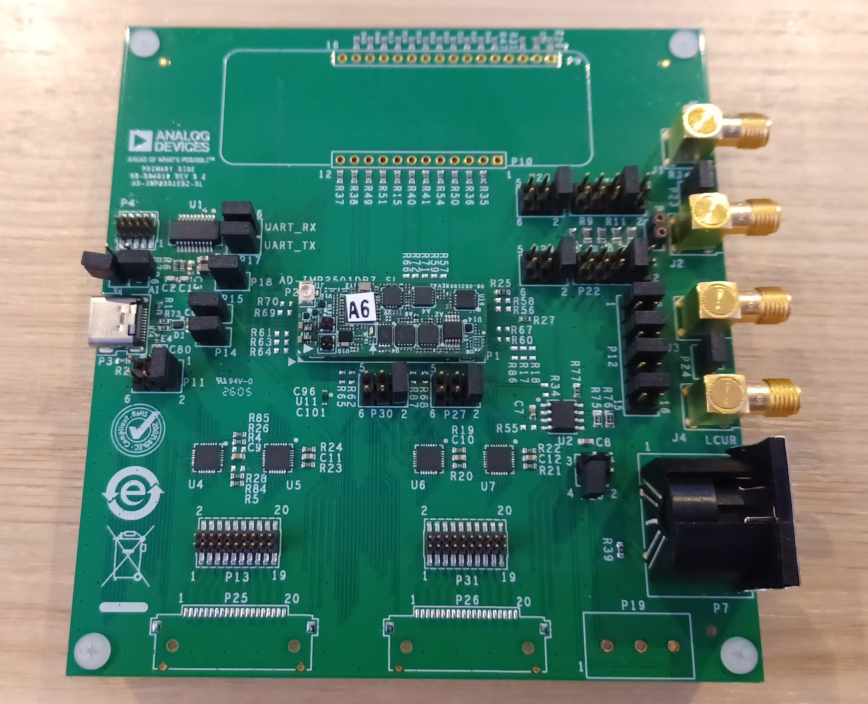
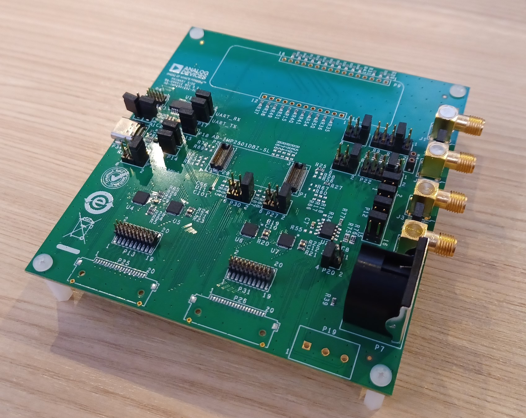
The AD-IMP2501EBZ-SL is the carrier board that allows for simplified host PC communication interfacing, varying electrical load connections, and easier setup/debug.
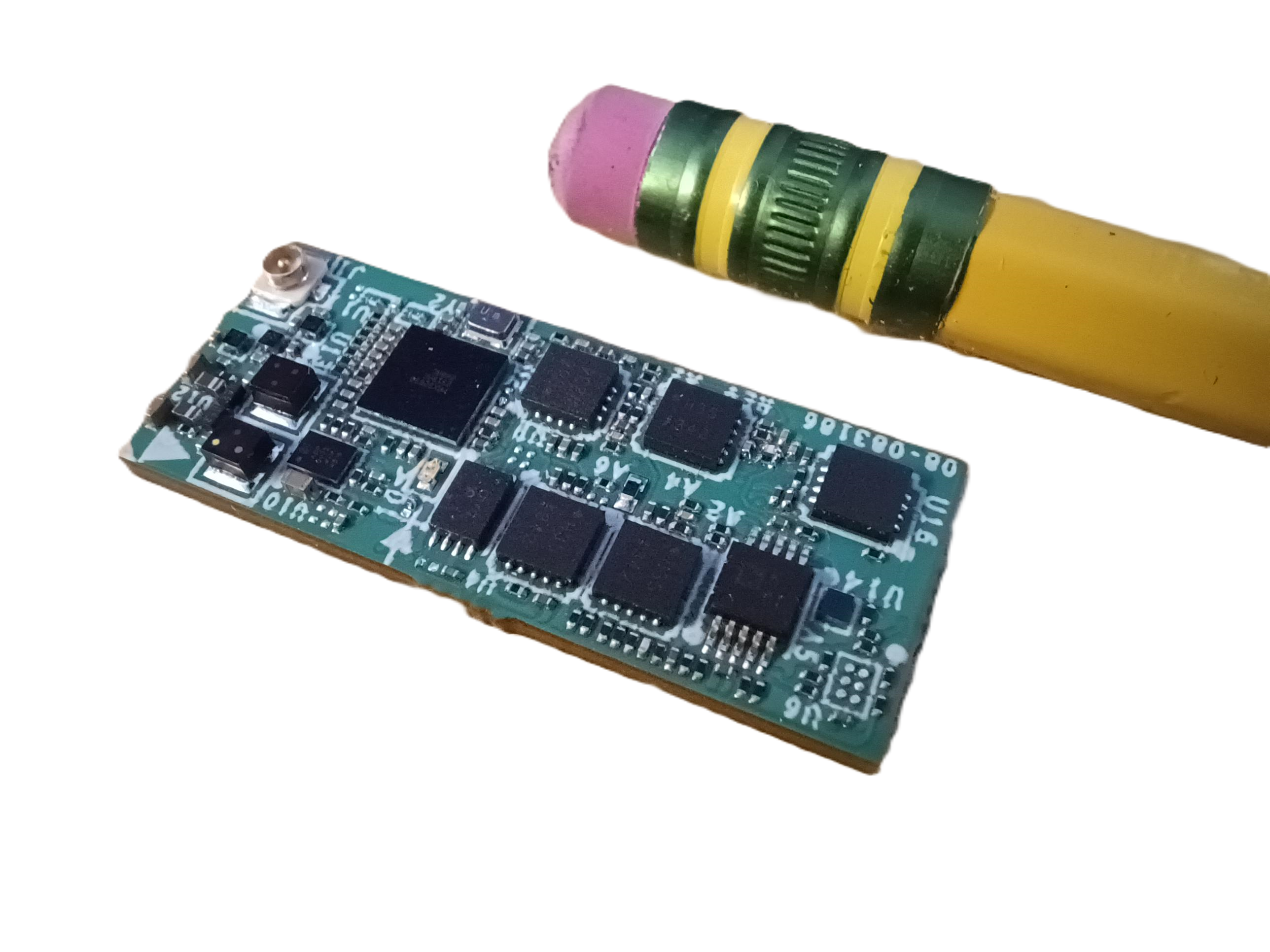
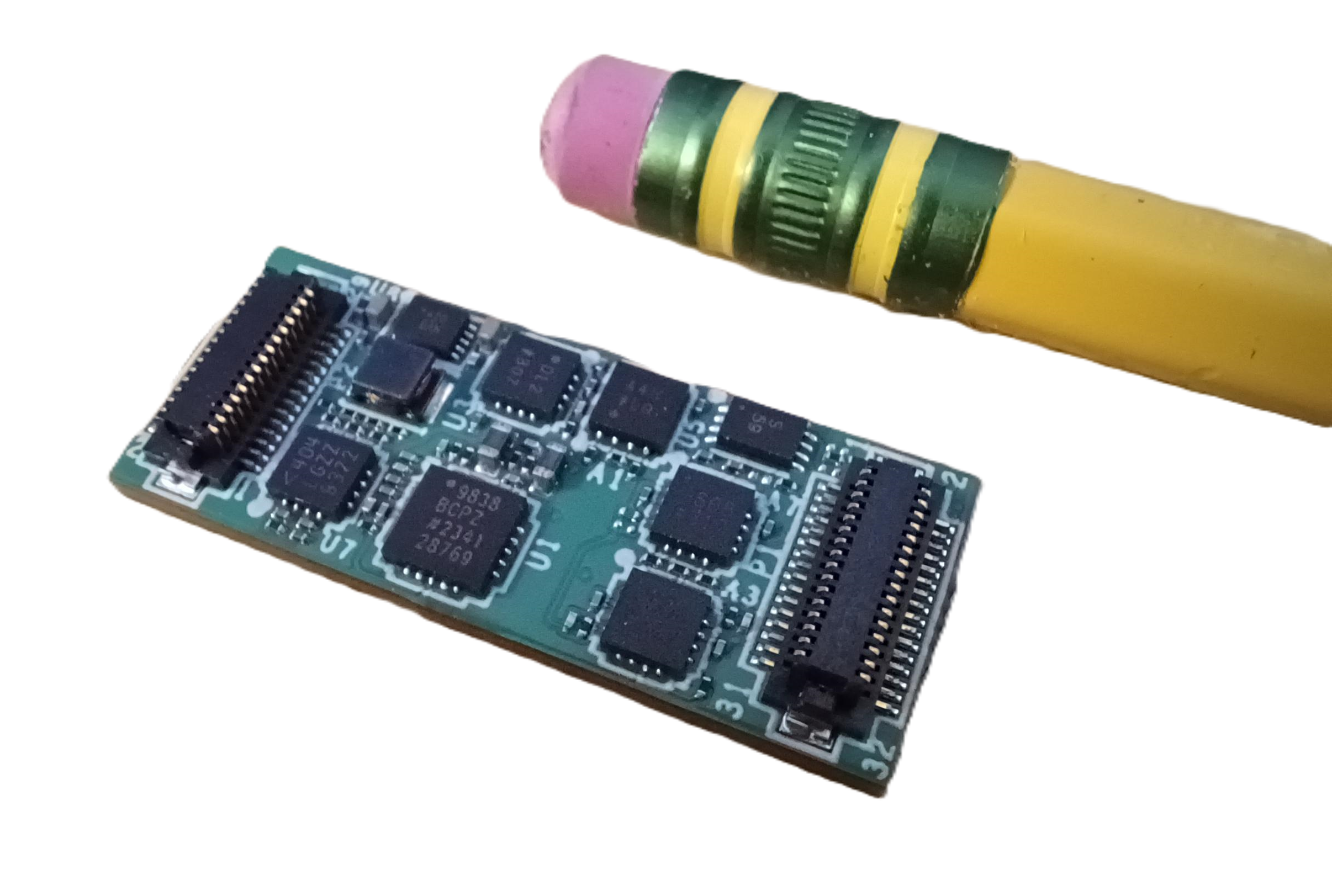
The AD-IMP2501DBZ-SL is the electrical impedance spectroscopy module, capable of tetrapolar impedance measurements. The module integrates AC waveform signal generation from 0V - 2.4V at 1 Hz up to 1.5 MHz, differential voltage measurement, current return measurement, and full impedance processing with a 120 MHz Arm Cortex-M4 microprocessor. All in a sub 400mm square PCB.
Features
AD-IMP2501DBZ-SL
High-performance, impedance analyzer measurement module.
Compact, 31.24mm x 12.83mm PCB
Impedance measurements from 1 Hz to 1.5 MHz
Voltage or Current excitation modes
16-bit acquisition channels
Operates from a single 5V supply
UART interface (additional BLE 5.2, USB, and SPI hardware support capable, not implemented)
Designed to help meet leakage requirements for IEC 60601-1*
6 display mode formats (R/X, Z/θ (deg), Z/θ (rad), G/B, Y/θ (deg), Y/θ (rad))
Command line, Graphical user interface, and Python API for easy system evaluation and data collection
*Current hardware implementation is dependent on voltage drive levels. The hardware can be modified to limit the current depending on application specifications and voltage drive needs
AD-IMP2501EBZ-SL
Easy-to-use evaluation and development board that enables convenient access to the functionality of the AD-IMP2501DBZ-SL Impedance Analyzer Measurement Module.
USB-C connector provides power and serial communication to host PC
On board FTDI USB to UART conversion
DIN and SMA connectors and for interfacing with an external load
On board loads with jumper configurations for testing and evaluation without external components or connections
Applications
Surgical Tools
Surgical Tissue Sensing
Medical Diagnostics and Life Sciences Devices
Bio-Z and Vital Signs Applications
Electronics Testing Systems
Chemistry Systems
Laboratory Bench-top Sensing Applications
Research in Industry or Academia
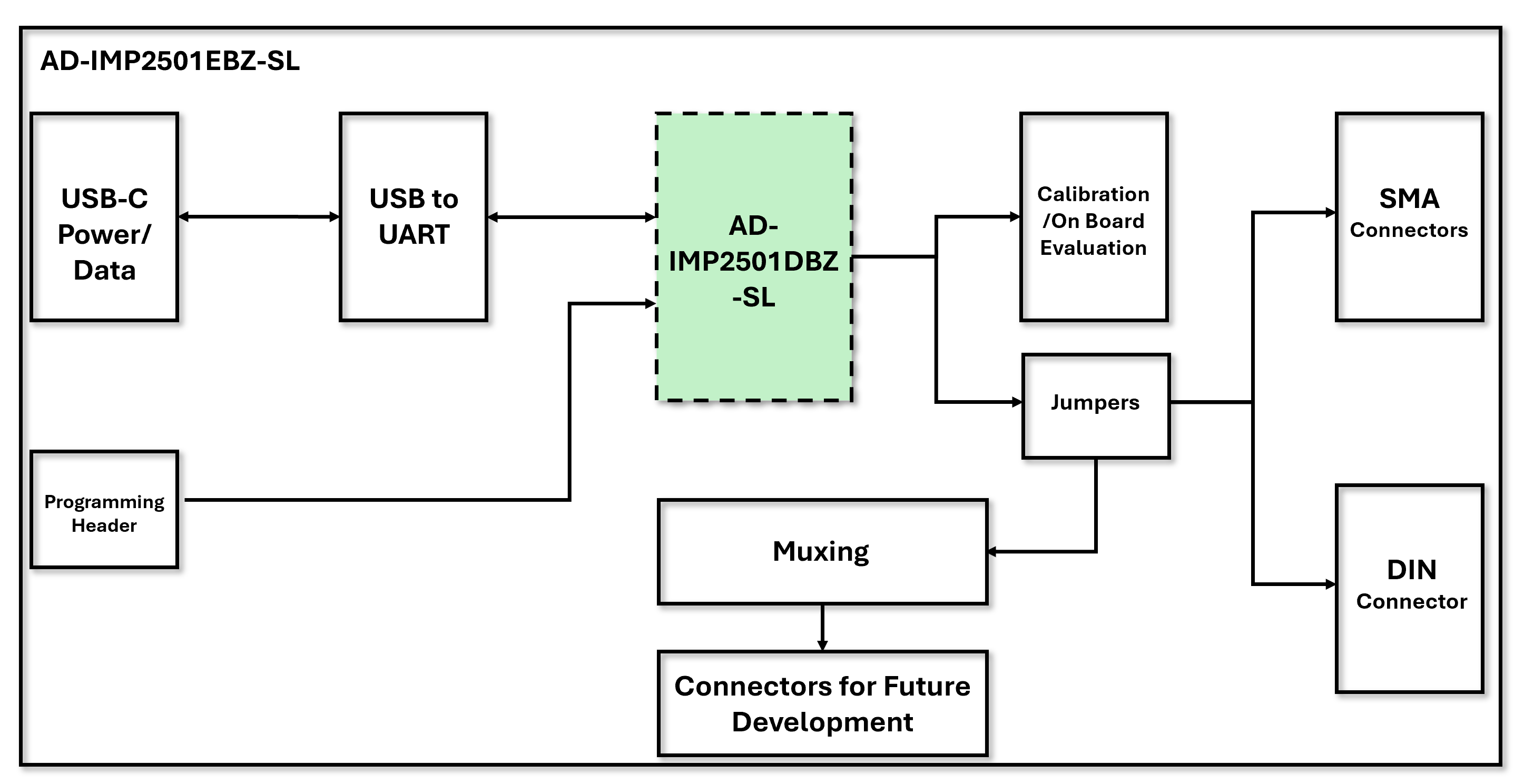
System Architecture
Specifications
TBD from the characterization table what we want to include here:
Parameter |
Min |
Typ |
Max |
Units |
|---|---|---|---|---|
Vin |
4.6 |
5 |
20 |
V |
Load Range |
0.1 |
500k |
Ohms |
|
Relative Accuracy |
0.2 |
0.015 |
% |
|
Iout |
mA |
|||
Vout |
0.01 |
2.4 |
V |
|
Samples/s |
250 |
|||
Frequency Range |
0.1 |
1500k |
Hz |
|
DC Offset |
-2.5 |
0 |
+2.5 |
V |
Package Contents
AD-IMP2501EBZ-SL
AD-IMP2501EBZ-SL Impedance Demonstration Board
USB Cable
AD-IMP2501DBZ-SL
AD-IMP2501DBZ-SL Impedance Analyzer Measurement Module
Important
It is critical to purchase both the AD-IMP2501DBZ-SL Impedance Analyzer Measurement Module and the AD-IMP2501EBZ-SL Impedance Demonstration Board. These are sold separately.
User guides
These steps below are the essential steps to start evaluating the AD-IMP2501DBZ-SL:
These steps are explained in detail in the following user guides: