User guide
The complete circuit note of the evaluation board can be found at CN0561 Circuit Note.
Additional documentation:
Hardware guide
Hardware configuration
Jumper settings
Jumper P10 - ASRC and SRC Mode selection
CLOSE - ASRC Mode: DCLK and ODR pins are Inputs
OPEN - SRC Mode: DCLK and ODR pins are Outputs
Jumpers P13 and P15 - Analog front end amplifier supply selection
CLOSE 1-2 & OPEN 2-3: On board +15V/-15V supply
CLOSE 2-3 & OPEN 1-2: External +15V/-15V supply from P14
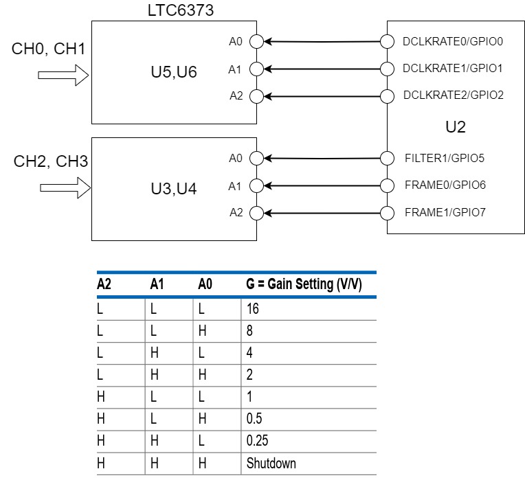
Instrumentation amplifier gain settings
Gain is controlled using GPIO functionality of AD4134 which is accessible using SPI.
Configure the GPIOs as output using the GPIO_DIR_CTRL register. Use the GPIO_DATA to write high and low levels on the pins.
Gain settings are the same for the group of CH0 & CH1, and for the group of CH2 & CH3.
LED indicators
DS1: Fault flag LED that glows when an input fault occurs on ADG5462F
Power supply
The EVAL-CN0561-ARDZ board can be powered through the following options:
Arduino connectors (P1, P2, P4, P5): 3.3V supplied by the host processor board.
P16: External power input: 9V to 12V.
P14: External +15V/-15V supply for the analog front end.
When using an FPGA carrier with FMC connectivity (e.g., ZedBoard), the power supply comes through the FMC connector (P3), given by the FPGA.
Analog inputs
The EVAL-CN0561-ARDZ board provides the following analog input options:
P6, P7: SMA connectors for IEPE sensor connection.
P8, P9: Analog inputs for data acquisition.
J6, J8: SMA connectors for analog inputs to channel 0.
J5, J7: SMA connectors for analog inputs to channel 3.
P11, P12: Optional connectors for analog inputs to channel 1 and 2.
To the SMA connectors, the source should be a low noise, audio precision signal (such as the Audio Precision audio analyzer).
Connectors
All connectors listed below provide extensive options for interfacing with the data acquisition board.
P1, P2, P4, P5: Arduino connectors
P17: Arduino Zio connector
P3: FMCZ connector
P6, P7: SMA connectors for IEPE sensor connection
P8, P9: Analog inputs for data acquisition
P16: External power input: 9V to 12V
P14: External +15V/-15V supply for analog front end
J6, J8: SMA connectors for analog inputs to channel 0
J5, J7: SMA connectors for analog inputs to channel 3
P11, P12: Optional connectors for analog inputs to channel 1 and 2
Arduino pin assignments
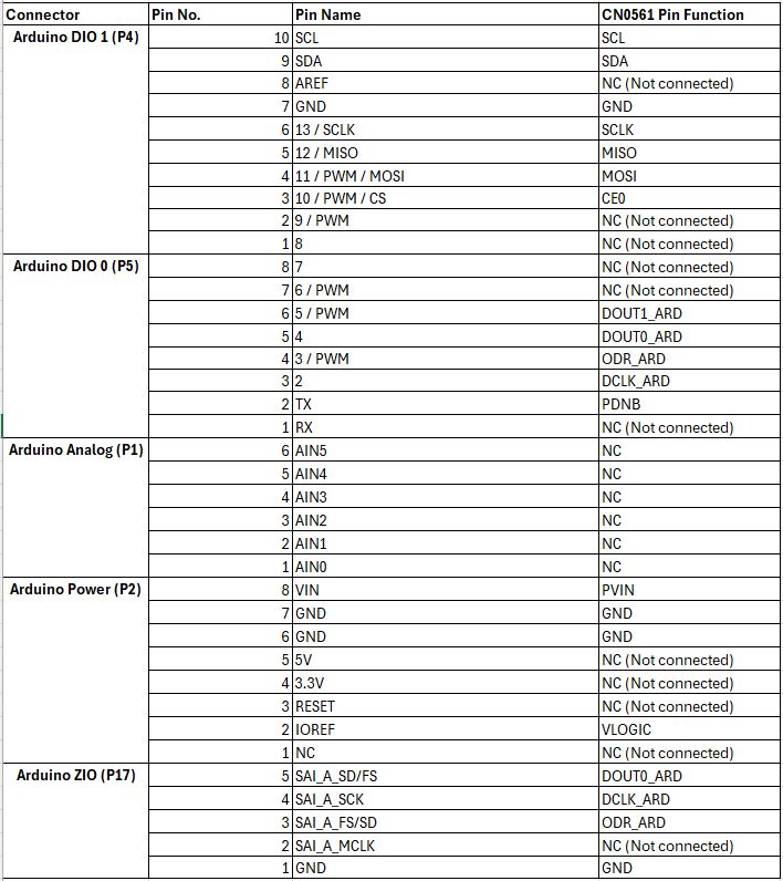
Host processor connector
Arduino and Zio Connectors: P1, P2, P4, P5 & P17. These connect to 3.3V Arduino boards.
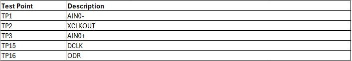
Test points
Data acquisition performance (SPI clock and sample rate)
The system is designed to acquire data from the ADC device, supporting continuous data capture at a maximum 1.5 MSPS data rate. However, due to a hardware limitation, the Cora Z7S variant will only support a maximum data clock of 24 MHz, in contrast with 50 MHz supported on the ZedBoard.
Schematic, PCB Layout, Bill of Materials
Software guide
The evaluation board is supported with the Libiio library. This library is cross-platform (Windows, Linux, Mac) with language bindings for C, C#, Python, MATLAB, and others. Two easy examples that can be used with it are:
Precision Converters firmware
For use with standalone microcontroller platforms, the Precision Converters firmware build guide is available at: