Nucleo-H563ZI Quickstart
Equipment Required
NUCLEO-H563ZI board
IIO Occilloscope Software
USB Type C to USB cable
Precision AC source (for example, AP2700, Brüel & Kjær, or similar precision sine generator)
Hardware Connection
The basic test setup requires the EVAL-CN0561-ARDZ board to be plugged into the Nucleo-H563ZI board. The Nucleo H563ZI board is required to capture and display the data. Software is available on this page: IIO Oscilloscope
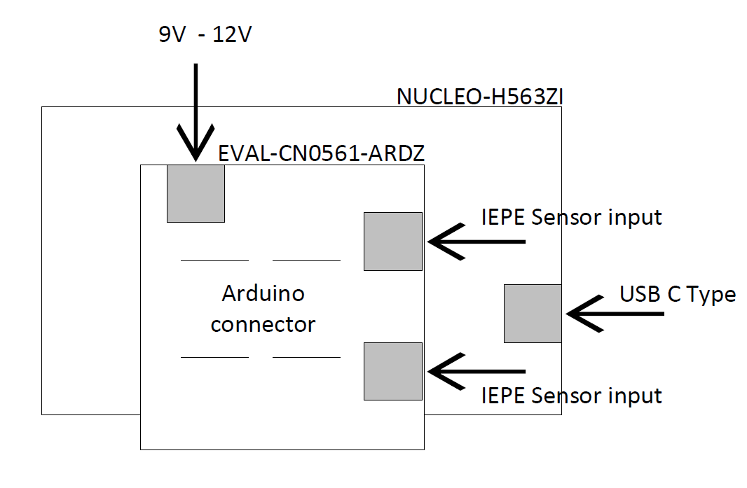
Mount the EVAL-CN0561-ARDZ evaluation board on the carrier board (NUCLEO-H563ZI) by plugging it into the Arduino header as shown below.
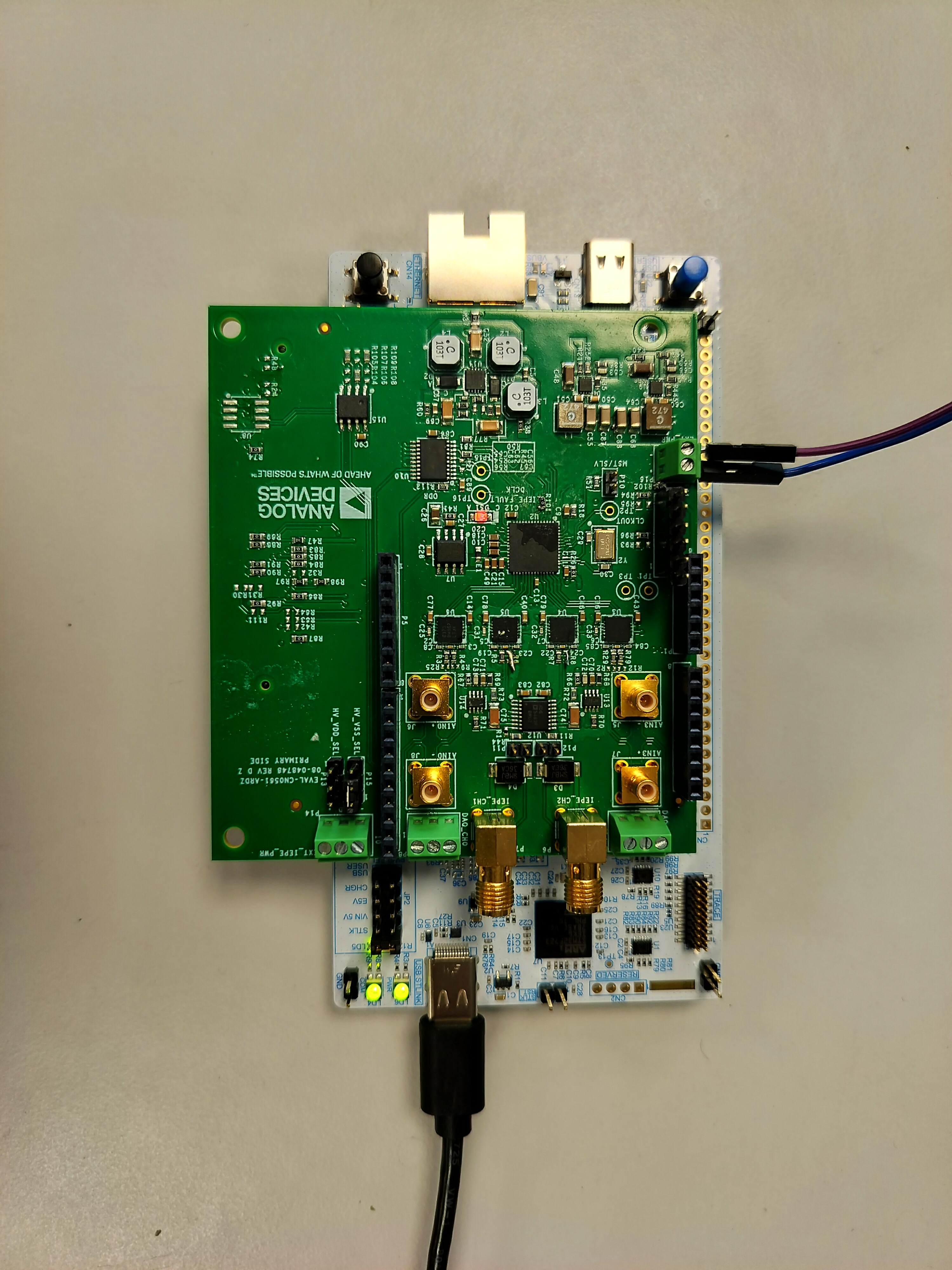
Figure 2 EVAL-CN0561-ARDZ mounted on the Nucleo-H563ZI board.
To test the basic functionality of the board, connect a precision, high quality sine wave or arbitrary waveform generator to the analog input connector of the EVAL-CN0561-ARDZ board.
Follow these steps to set up the EVAL-CN0561-ARDZ and the associated software:
Connect the USB-C cable to the Nucleo-H563ZI board and to a USB port of your laptop.
Connect a 12V power supply to the CN0561-ARDZ P16.
The connected green LED lights up on the NUCLEO-H563ZI board, next to the USB-C connector.
Give analog input signal using the connectors J6 and J8 on the EVAL-CN0561-ARDZ analog input SMA connectors
Open the file explorer and open folder NOD_H563ZI. Copy the file EVAL-CN0561-ARDZ.bin to the above folder. The file in the folder will disappear and file explorer will be closed automatically once the file is copied.
The USB connection creates a COM Port to connect to IIO Oscilloscope GUI running on windows-os. The COM port assigned to a device can be seen through the device manager for windows-based OS.
Open the IIO Oscilloscope Connection and select the COM port for Nucleo-H563ZI. Select the COM port and board rate 230400. Click the Refresh button.
IIO OSC shows the device name. Then click Connect button.
Select the AD4134 from the device name drop down
Power-on the sine or arbitrary waveform generator using the following steps:
Set the signal type to sine wave.
Set level to 1V p-p at 1kHz.
Enable the output.
Run the software and capture the resulting ADC data and FFT data
Go to Capture Window and Press Enable all button