ZED Quickstart with ACE Evaluation
Evaluation Board Kit Contents
EVAL-ADAQ8092-FMCZ evaluation board
Micro-SD memory card (with adapter) containing system board boot software and Linux OS
Equipment Needed
PC with Windows 7 or Windows 10 operating system
EVAL-ADAQ8092-FMCZ
Digilent ZedBoard with 12 V wall adapter power supply
Power Supply
Rohde & Schwarz SMA100A (clock source) - Suggested
Keysight 336xx series (signal generator) - Suggested
DC1075B (Clock Divider) - Suggested
SMA Cables
Attenuator
TTE Bandpass Filter - centered on test signal frequency - Suggested
SD card
SMA Adapter (Male-Male)
Getting Started
Download and install the ACE Software tool from the ACE download page. If ACE is already installed, make sure you have the latest version by using the ‘Check For Updates’ option in the ACE sidebar.
Run ACE and select ‘Plug-in Manager’ from the ACE sidebar to install the board plug-in that supports the Product Evaluation Board and select Available Packages. You can use the search field to help filter the list of boards to find the relevant one. An ACE Quickstart guide is available here: ACE Quickstart - Using ACE and Installing Plug-ins.
Insert the EVAL-SD-KUIPERZ SD card into the SD card slot on the underside of the ZedBoard.
Note
If there is a need to re-image or create a new SD card, instructions are available here: ADI Kuiper Linux with support for ACE Evaluation.
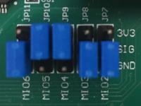
Ensure the ZedBoard boot configuration jumpers are set to use the SD card as shown.
Warning
To avoid potential damage, ensure the VADJ SELECT jumper is set to the correct voltage for the Product Evaluation Board.
Connect the Product Evaluation Board to the FMC connector on the ZedBoard.
Note
There may be additional steps and hardware required for a given Product Evaluation Board, such as function generator connections and setup. This information may be included with the eval kit or in the User guide for the corresponding Product Evaluation Boards page that can be found by searching Product Evaluation Boards and Kits.
Connect the USB cable from the PC to the J13/USB OTG port and the PSU to J20/DC input.
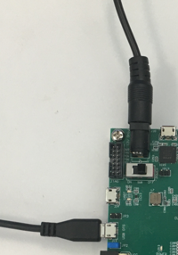
Slide SW8/POWER switch to the ON position. The green LD13/POWER LED should turn on.
The blue LD12/DONE LED & red LD0 LED should start blinking ~20-30 seconds later which indicates the boot process is complete.
Note
Linux versions prior to ADI Kuiper Linux for Evaluation version 2024-8-27 will instead boot with the BLUE LD12/DONE LED blinking immediately and LD7 blinking after ~20-30 seconds. This may indicate that an improved version of the ACE plugin is available if the SD-Card is updated to the latest version.
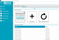
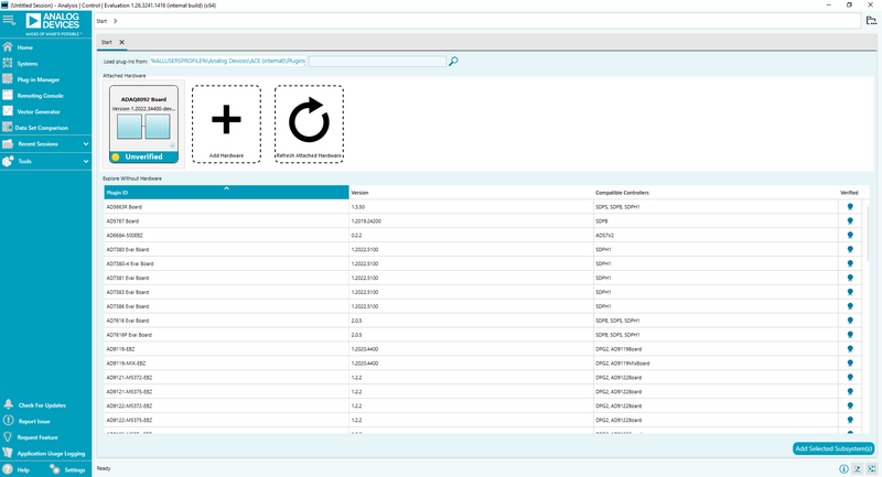
Launch the ACE software from the Analog Devices folder in the Windows Start menu. The Evaluation Board should appear in the ACE Start Tab » Attached Hardware view.
See also
For more details on the ADI Kuiper Linux for Evaluation setup, see ADI Kuiper Linux for Evaluation - Getting Started.
Evaluating Board Hardware
Setting up the board
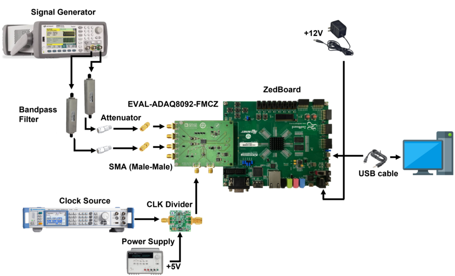
The figure above illustrates the evaluation system components. To use the system, follow these steps:
Connect the evaluation board to the ZedBoard. Ensure that there’s an SD card installed on it.
Connect the CLK divider (DC1075B) to the evaluation board
Connect a micro-USB cable to the USB OTG port
Apply power to the ZedBoard and to the DC1075
Open the ACE software
Apply the desired CLK and input signal
Start the evaluation
Controller Board
The ZedBoard, which is the system controller board, enables the configuration of the ADC and capture of data from the evaluation board by the PC via USB (or Ethernet). The ADAQ8092 supports a multi-lane serial port interface (SPI) for each data converter channel. The SPI interface for each channel is connected to the ZedBoard via the FMC connector (P1). The ZedBoard™ functions as the communication link between the PC and connected evaluation board. It buffers samples captured from the evaluation board in its DDR3 memory. The ZedBoard requires power from a 12 volt wall adapter (included with the ZedBoard). It hosts a Xilinx® ZYNQ® 7020 SoC, which contains two ARM® Cortex-A9 Processors and a Series-7 FPGA with 85k Programmable Logic cells. A Linux OS runs on the host processor system. It communicates with the PC through either a USB 2.0 high speed port or a 10/100/1000 Ethernet port. The default software configuration uses USB.
Software Support
The ADI ACE application provides a ‘plug and play’ evaluation experience, enabling users to get up and running quickly with the product evaluation board. ACE can configure the embedded software on supported controller boards and provides a quick and easy way to get set up, configure the board and perform data capture and analysis and/or waveform generation. For ACE installation and documentation instructions see ACE. Make sure to follow the instructions to install the necessary evaluation board plug-in support.
If the machine that ACE is installed on has internet access, you can find/install/update plug-ins directly from the ACE application. For environments without internet access, you can download these plug-ins from the previous link to portable storage and install them into ACE.
Note
Product-specific documentation for the evaluation software can be found within the ACE plug-in. The controller board supported by ACE with this product evaluation board is the ZedBoard™.
Software Operation
To start the ACE evaluation software, follow these steps:
Open the ACE software.
In the Start window, wait until the software recognizes the “ADAQ8092 Board” as an attached hardware, and then double-click on it to go to the “ADAQ8092 Board” window.
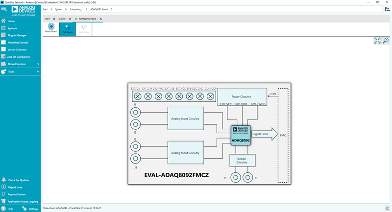
In the ADAQ8092 Board window, double-click the “ADAQ8092” icon from the block diagram to go to the “ADAQ8092” chip window.
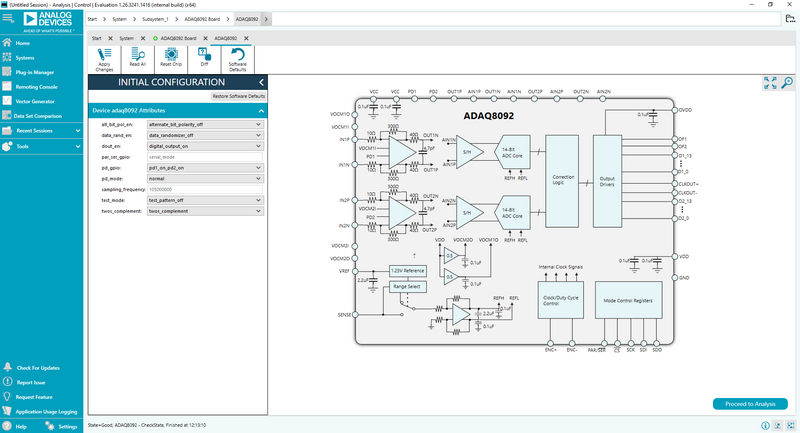
In the ADAQ8092 chip window, click “Proceed to Analysis” to start the evaluation.
Note
Here you can change the device attributes before starting the evaluation such as: alt_bit_pol_en, data_rand_en, dout_en, pd_gpio, pd_mode, sampling_frequency, test_mode, and twos_complement.
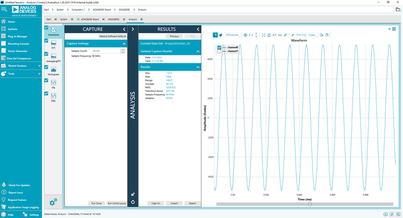
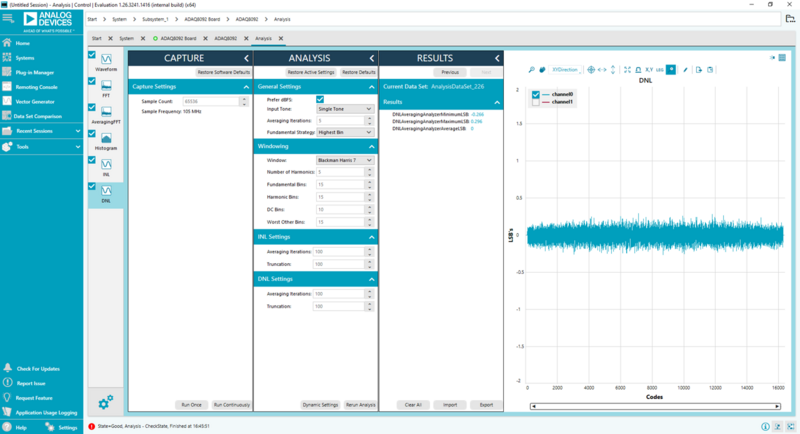
Here in the ANALYSIS window, there are three (3) panes, the CAPTURE pane, ANALYSIS pane, and RESULTS pane.
In the CAPTURE pane, the user can change the sample count up to 65536 and the sample frequency used is shown. At the bottom, the user can capture data once by clicking “Run Once” or continuously by clicking “Run Continuously”.
Note
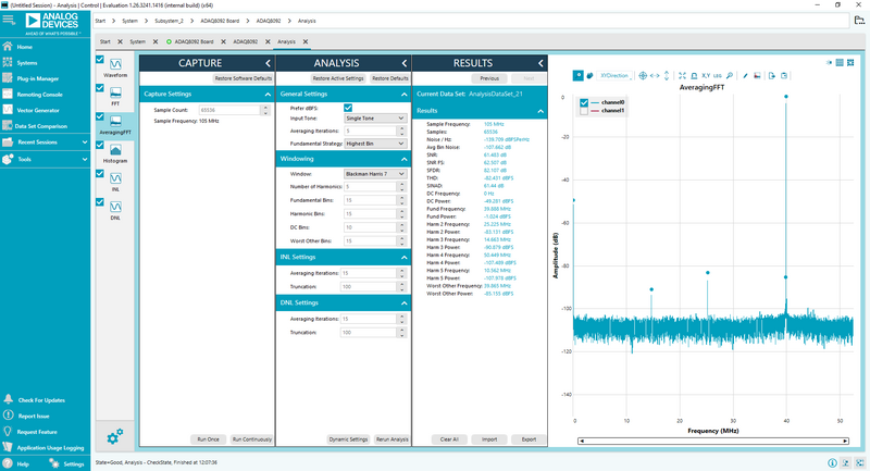
Use “Run Continuously” when capturing the Average FFT, INL, and DNL.
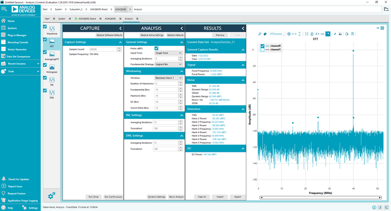
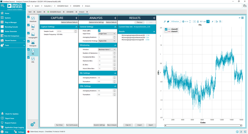
In the ANALYSIS pane, the user can change the “windowing” type of the FFT, and also the “average iterations” when capturing the INL and DNL performance. When measuring the INL and DNL, the user should use the “Run Continuously” function and wait until it reaches the number of “average iterations” placed.
In the RESULTS pane, this is where the parametric values will be displayed. At the bottom of it, the user can import or export the data.