User guide
Hardware guide
Hardware configuration
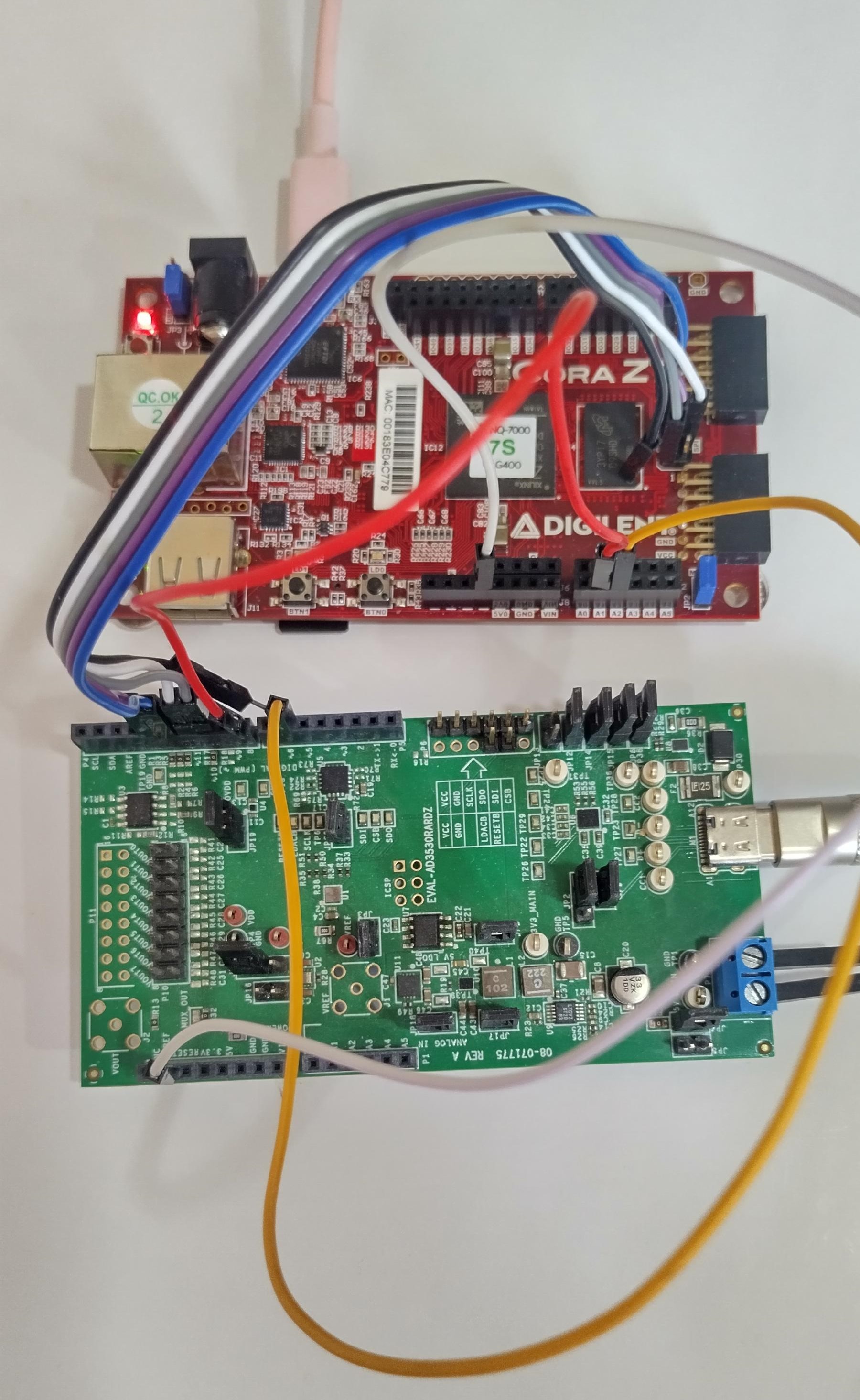
The EVAL-AD3530R and EVAL-AD3531R evaluation boards expose an SPI interface and GPIO signals that connect to the FPGA carrier. The tables below list the signal mapping for each supported carrier.
Carrier-specific setup
CoraZ7s
Place a jumper on JP2, shorting the two pins together. Select the JP3 connection depending on the power supply source (USB or external).
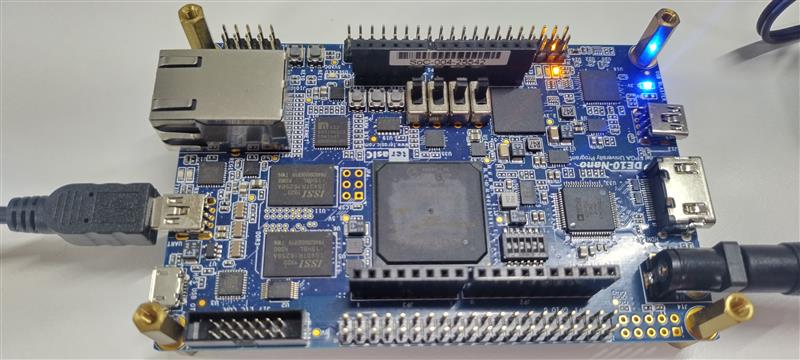
DE10-Nano
Adjust the FPGA configuration mode switch (SW10) to the SD card boot position.
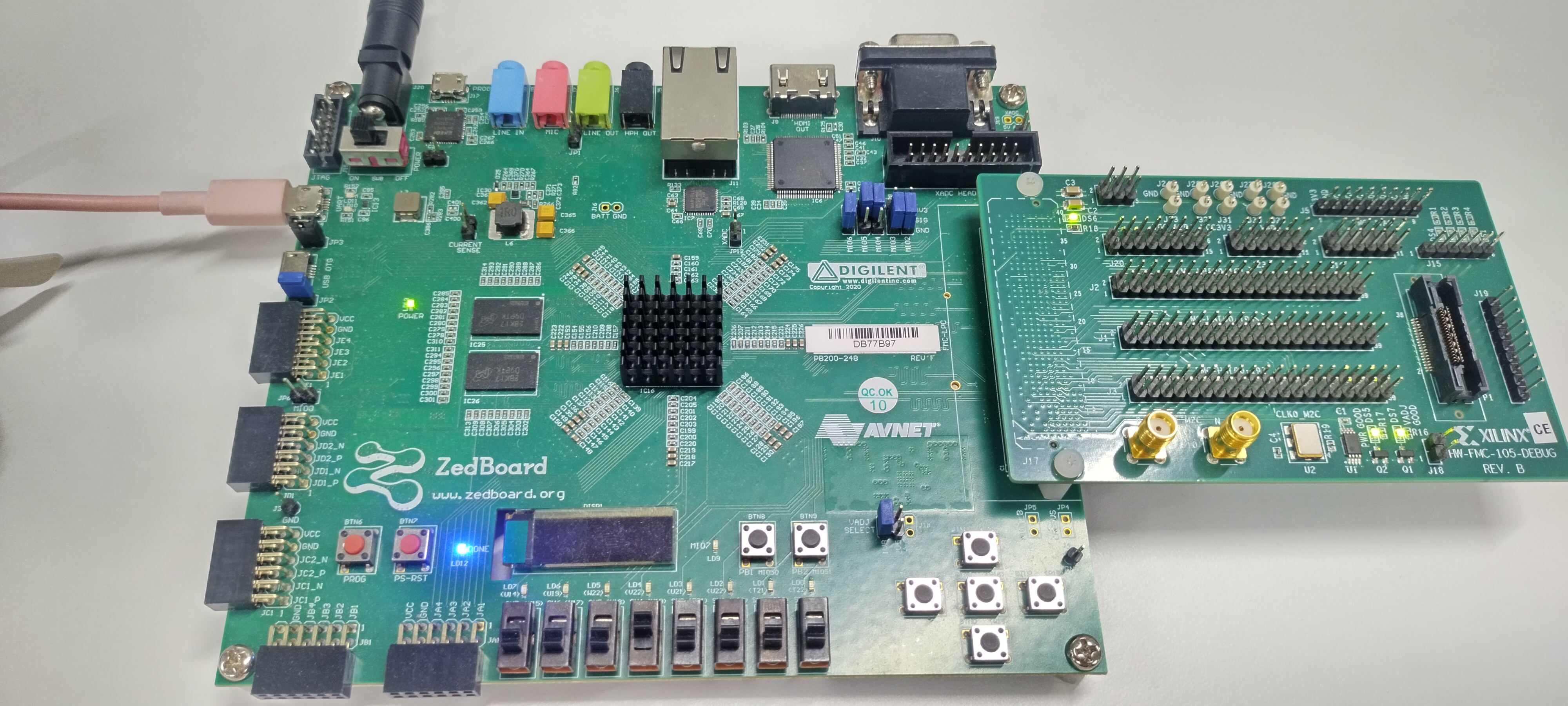
ZedBoard
Set jumpers MIO[6:2] to 01100. VADJ must be set to 2.5 V.
The ZedBoard FMC connector is low pin count.
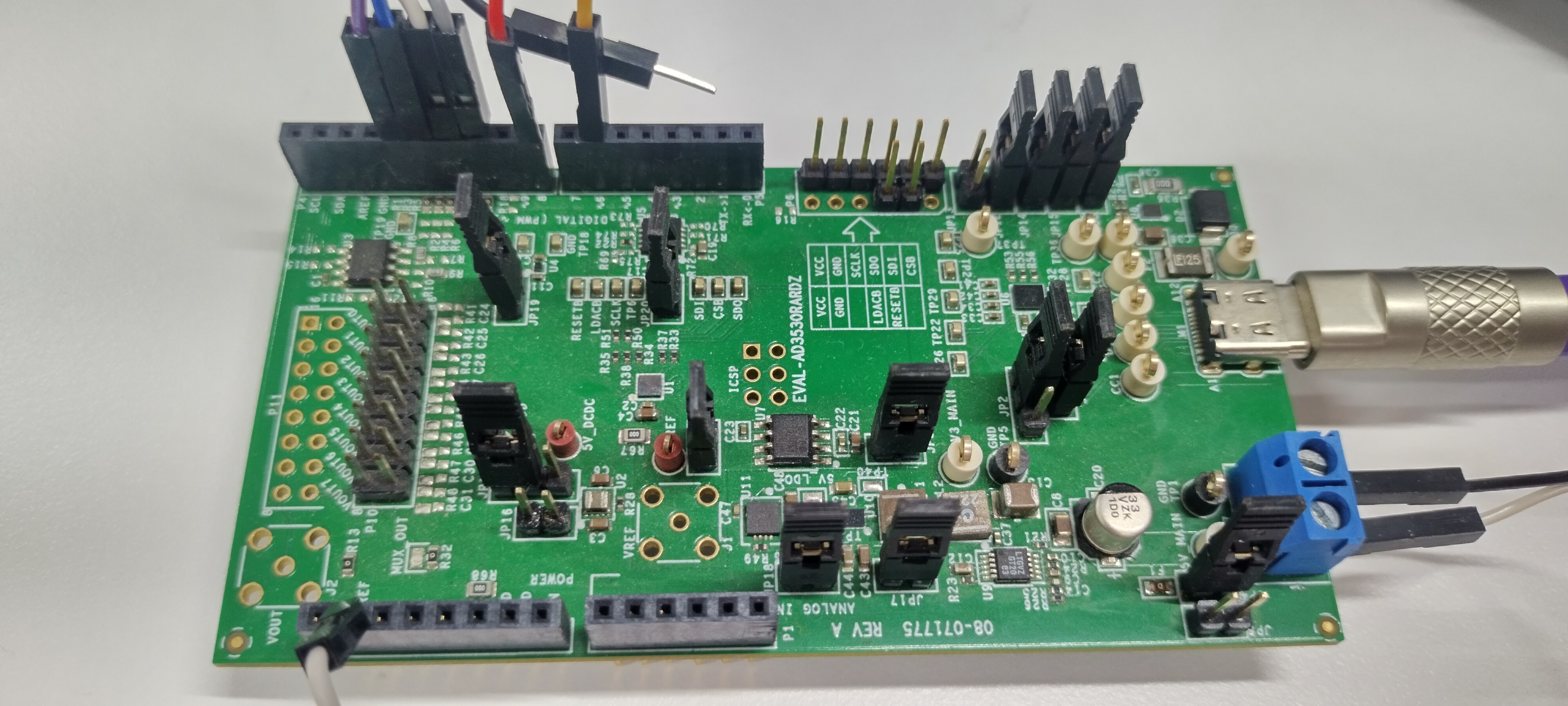
Power supply
The evaluation board operates from a single 2.7 V to 5.5 V supply. Power can be provided via the USB-C connector, the terminal block, or through the SDP-K1 controller board.
Schematic, PCB layout, bill of materials
Design support files for the evaluation boards are available on the respective product pages:
Software guide
Driver
The AD3530R/AD3531R is supported by the Linux IIO subsystem via the
ad3530r driver.
File |
Link |
|---|---|
Driver |
|
DT bindings |
Once the system has booted, IIO-based tools can be used to interact with the device: